Want to stream your vinyl to AirPlay speakers without extra boxes or messy cables?
This project shows how to convert a fully automatic 1980s Technics turntable into a self-contained AirPlay streamer using autostream.
Fully automatic, direct-drive turntables with built-in wireless streaming simply don’t exist today—this build creates one by embedding autostream directly inside a Technics SL-D303 turntable, creating a seamless, single-box wireless record player.
What This Build Delivers
- Fully automatic vinyl playback – drop the needle, music plays via AirPlay speakers
- No external boxes, cables, amps or apps
- Original look and controls preserved
- Always-on, instant playback
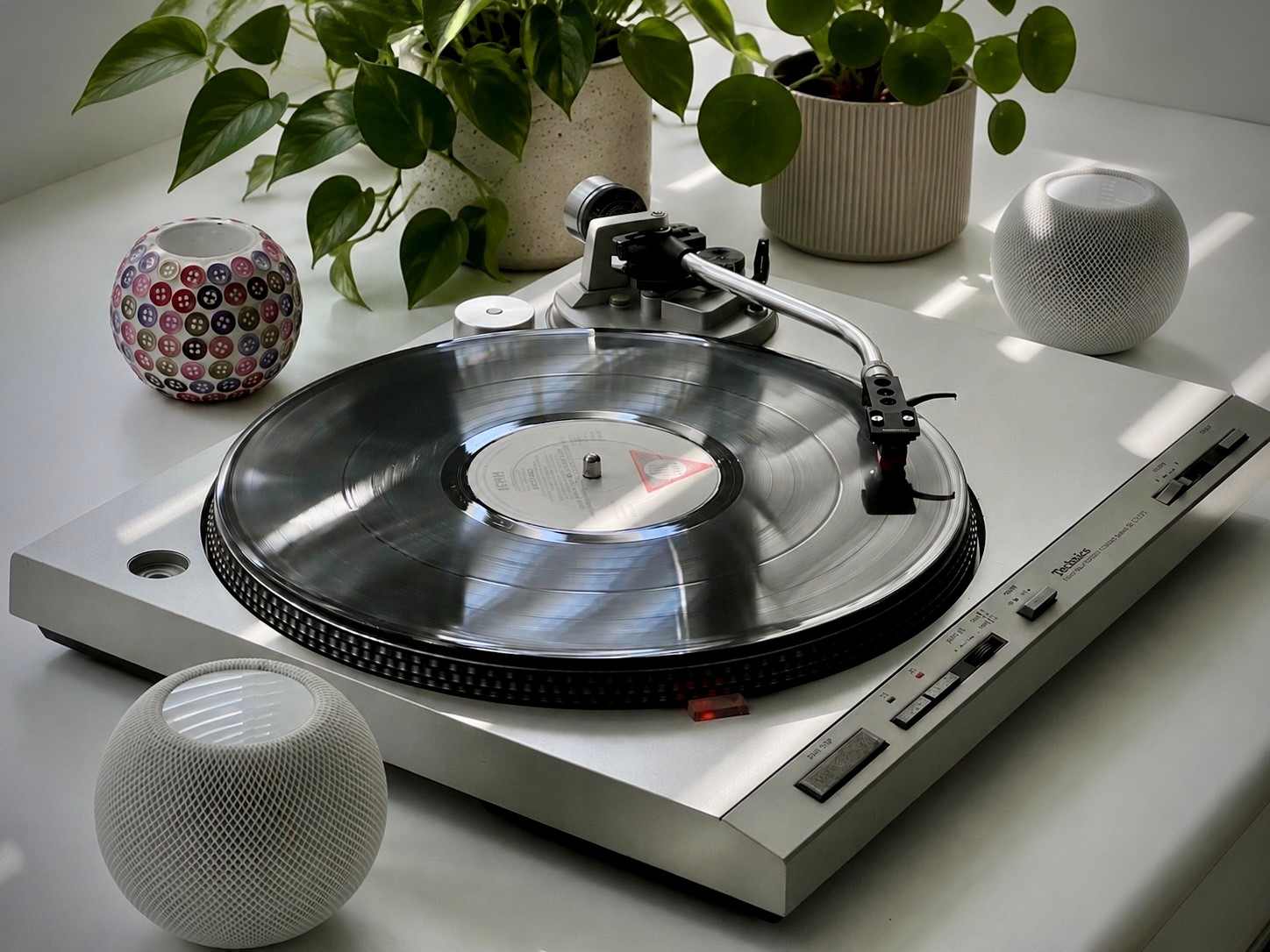
This build uses autostream with a Technics SL-D303 – a fully automatic, direct-drive turntable from the early 1980s – to create perhaps the ultimate wireless record player.
It’s minimalist Hi-Fi – just the turntable and any number of AirPlay speakers anywhere in or around the home. The tactile pleasure of choosing a record, played directly to your AirPlay speakers. No amplifiers, no trailing speaker cables, and no restriction to one room.
The Technics SL-D303
Freshly serviced and with new capacitors on its servo control board, the SL-D303 provides essentially SL-1210 level stability and rumble, with the added benefit of being fully automatic.
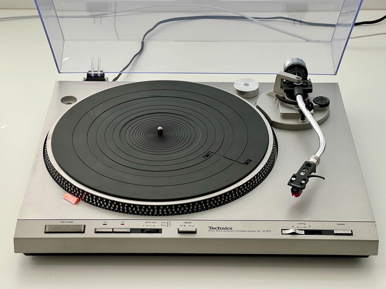
It’s ideal for this resto-mod where we’re focused on simplicity of user experience and, having an ABS (plastic) chassis, the Wi-Fi signal travels straight out easily. There are a number of similar decks made around this area that likely share the same chassis, some with Quartz lock (SL-Q series).
System Overview
This is what we’re building:
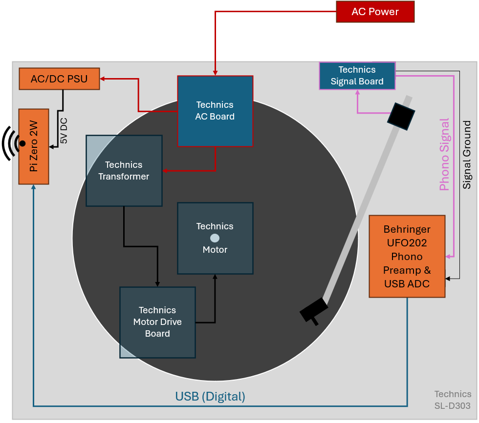
New components (in orange) will be installed within the chassis – providing one mains cord, no external boxes or old iPads, and absolutely no visible modifications. It looks and works just like it should, only we skip the amplifiers and wires and playback via AirPlay anywhere in the house.
⚠️ Safety Warning: If you’re not confident working inside mains-powered equipment, stop right here and seek help. Live mains parts are exposed in this machine with the base removed. This mod shows the connection of a SMPS to the player’s original AC mains input to provide always-on operation. A suitable, internally fused and thermally protected SMPS is needed. You alone are responsible for the safety of your finished project.
Step 1: Refurb
This deck is over 40 years old. Refurb is relatively easy and well worth the effort:
- Clean and regrease the mechanism. Fortunately the automatic mechanism comes off in one piece without exploding into a million pieces. It can be cleaned off with an Isopropynol spray then re-greased with something like SuperLube 21013. There are various greasing points under the tonearm too – some good videos on YouTube help.
- Oil the shaft and base bearing using a suitable fully synthetic ISO 68 turntable oil
- Replace all the servo board electrolytic capacitors
- Replace the cartridge (VM95ML used here)
Step 2: Audio Capture
Signal first. The challenge is fitting a phono preamp inside a very tight space without introducing noise.
There’s not a lot of space in the slim-line Technics, so we’re limited in choice. The Behringer UFO202 is about the smallest turntable compatible USB preamp (with the necessary RIAA EQ) available and can be easily removed from its plastic case, but the Technics’ cueing mechanism is right where we need it to be.
To solve this, some 3D printed levers can replace the original parts and lift the cueing rod just enough to provide the clearance we need. The UFO202 board itself is mounted on a 3D printed base plate glued to the ABS chassis. PETG works well for both parts and UHU glue is strong enough for the base plate, with a couple of tiny M2.5 screws securing the board.
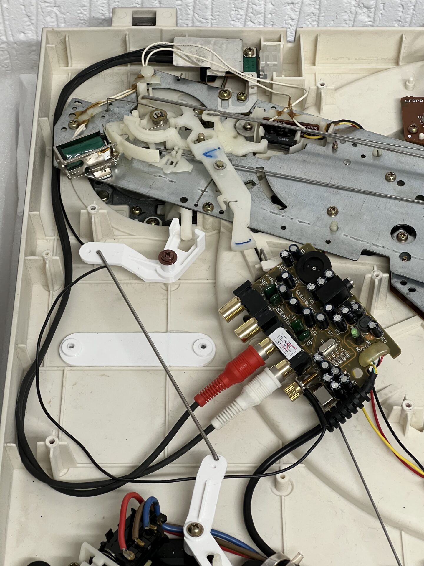
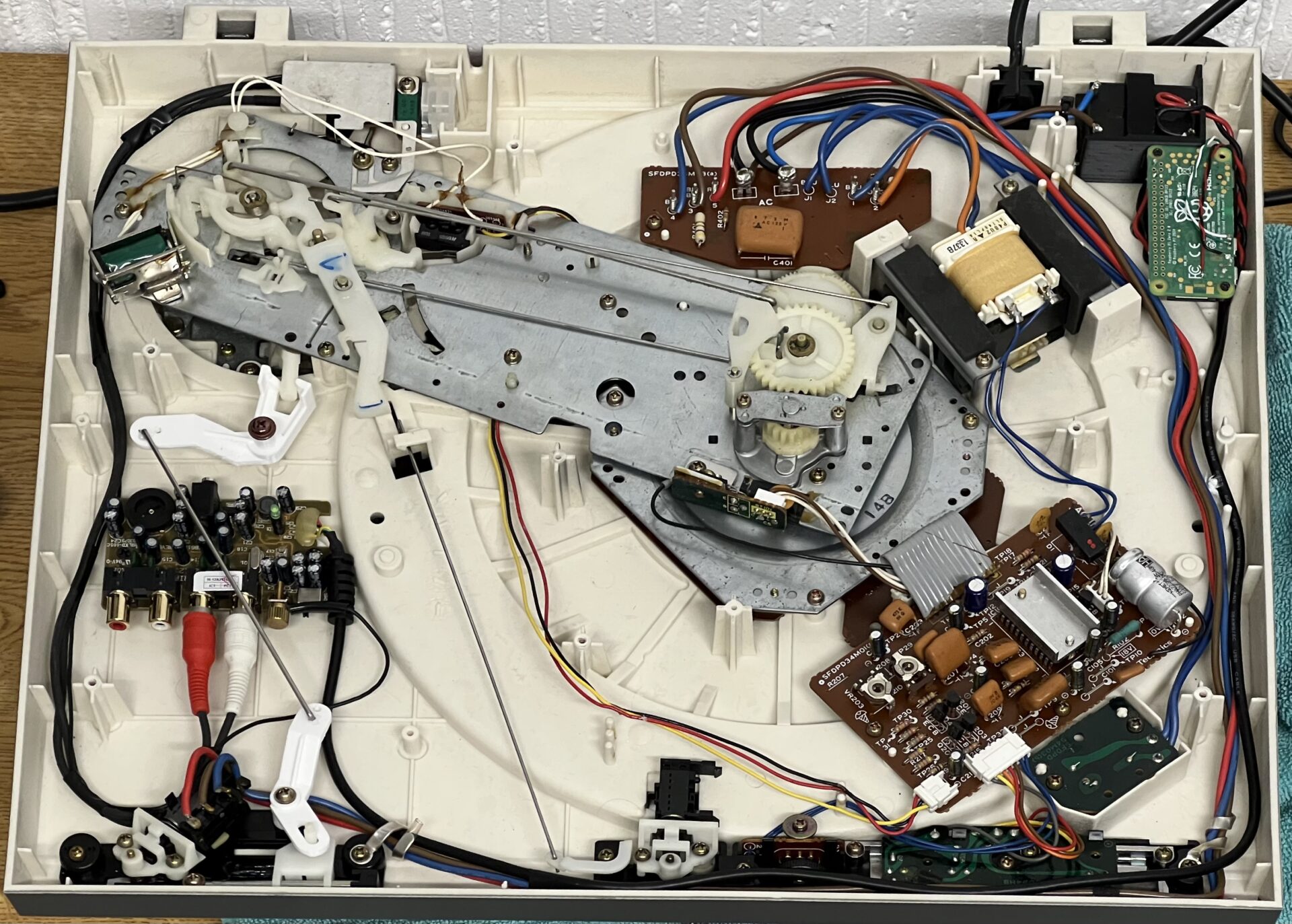
The Technics signal cables can be resoldered to the tonearm PCB (under the metal shield at the top of the photo above) to run to the left rather than out the back of the turntable on it’s right, making connection to the preamp neat and the whole thing invisible from the outside with no dangling wires.
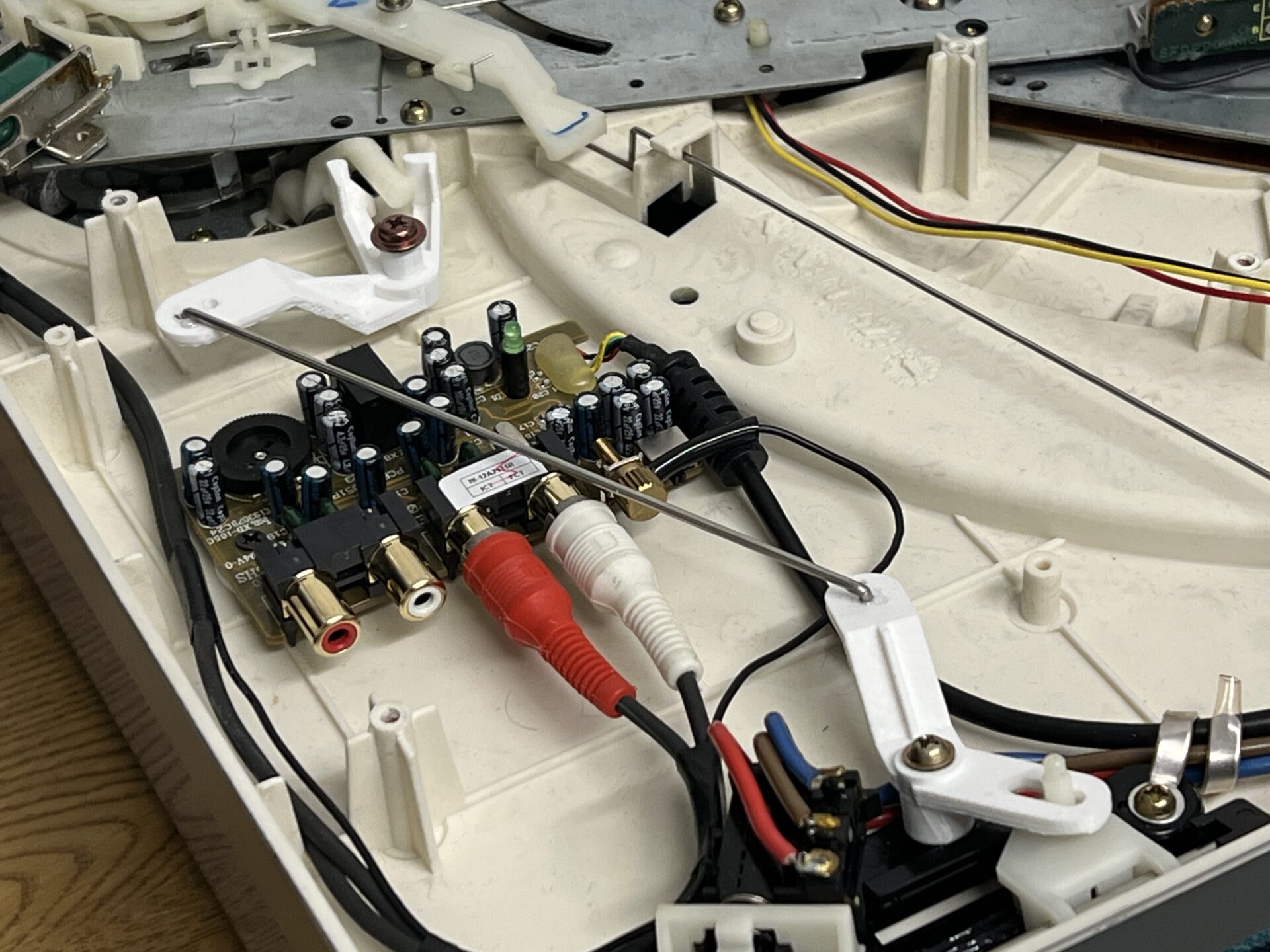
Under the tonearm seemed the best choice as it keeps the low-level signal path shortest, and away from the Raspberry Pi and its power-supply we’ll get to next. Here it is screwed down in place with the cueing arm raised up over it:
These 3D printable parts will be available on Printables soon.
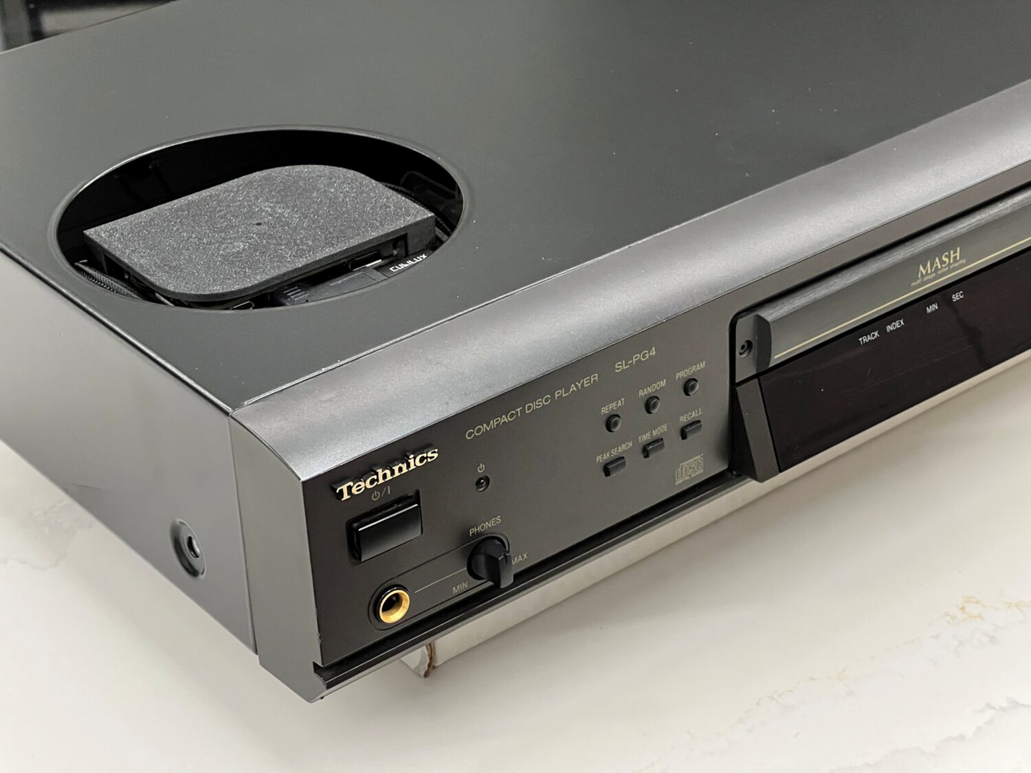
The end result – No loss of functionality, clean internal layout, and totally hidden pre-amp/USB.
Step 3: Raspberry Pi Installation
The factory PSU in the technics is already powering sensitive servo control and has unknown headroom. The only real option is to add a tiny 5-Watt switched-mode power-supply (SMPS) for the Raspberry Pi, but digital electronics inside a turntable, and especially SMPSs, can easily ruin everything because of the noise they potentially generate. The UFO202 links digital and audio ground, making the potential for noise coupling even worse.
Fortunately, we now have a wide range of tiny, encapsulated AC to DC PSUs available and medical-grade modules like the XP Power EME05US05 provide low noise (50mV peak-to-peak), a wealth of safety features, and with a switching frequency of 130kHz operate well outside of anything that will upset the sensitive phono pickup.
Capacitive isolation from the mains input is also important. Using lesser PSUs, we can end up with that slightly weird tingly feeling when touching the tonearm (similar to touching an early metal MacBook on charge). Prototyping with the Raspberry Pi official PSU ran in to exactly this issue.
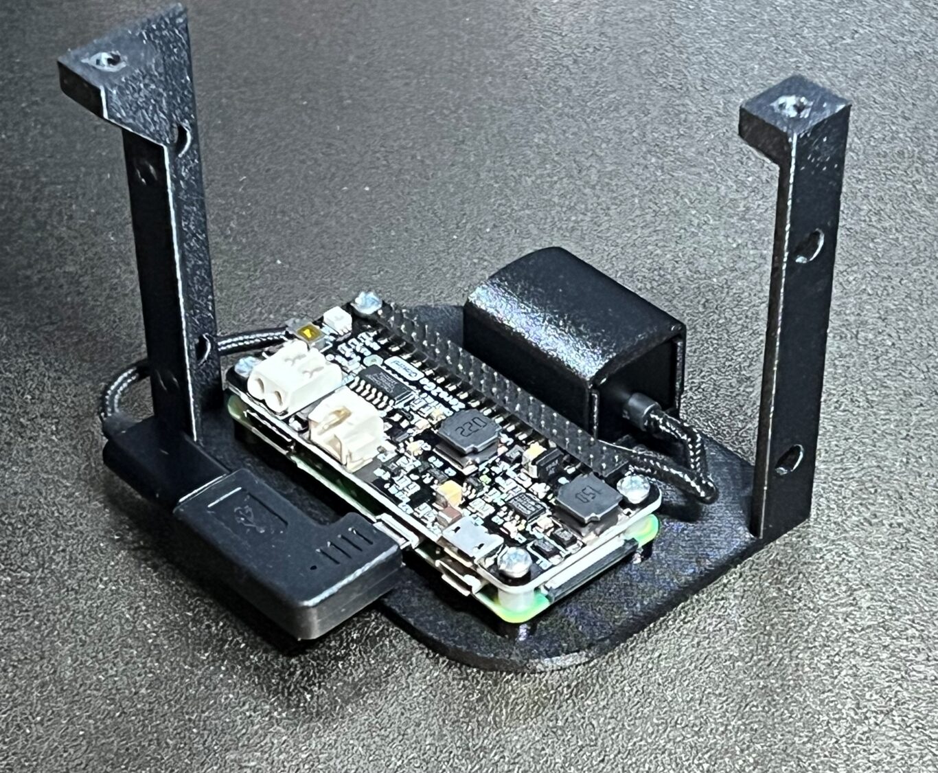
To mount the SMPS and the Pi, Technics helpfully left a little space at the back of the machine and a mounting point that a 3D printed bracket can be used with. The mount secures both the SMPS and the Pi in one:
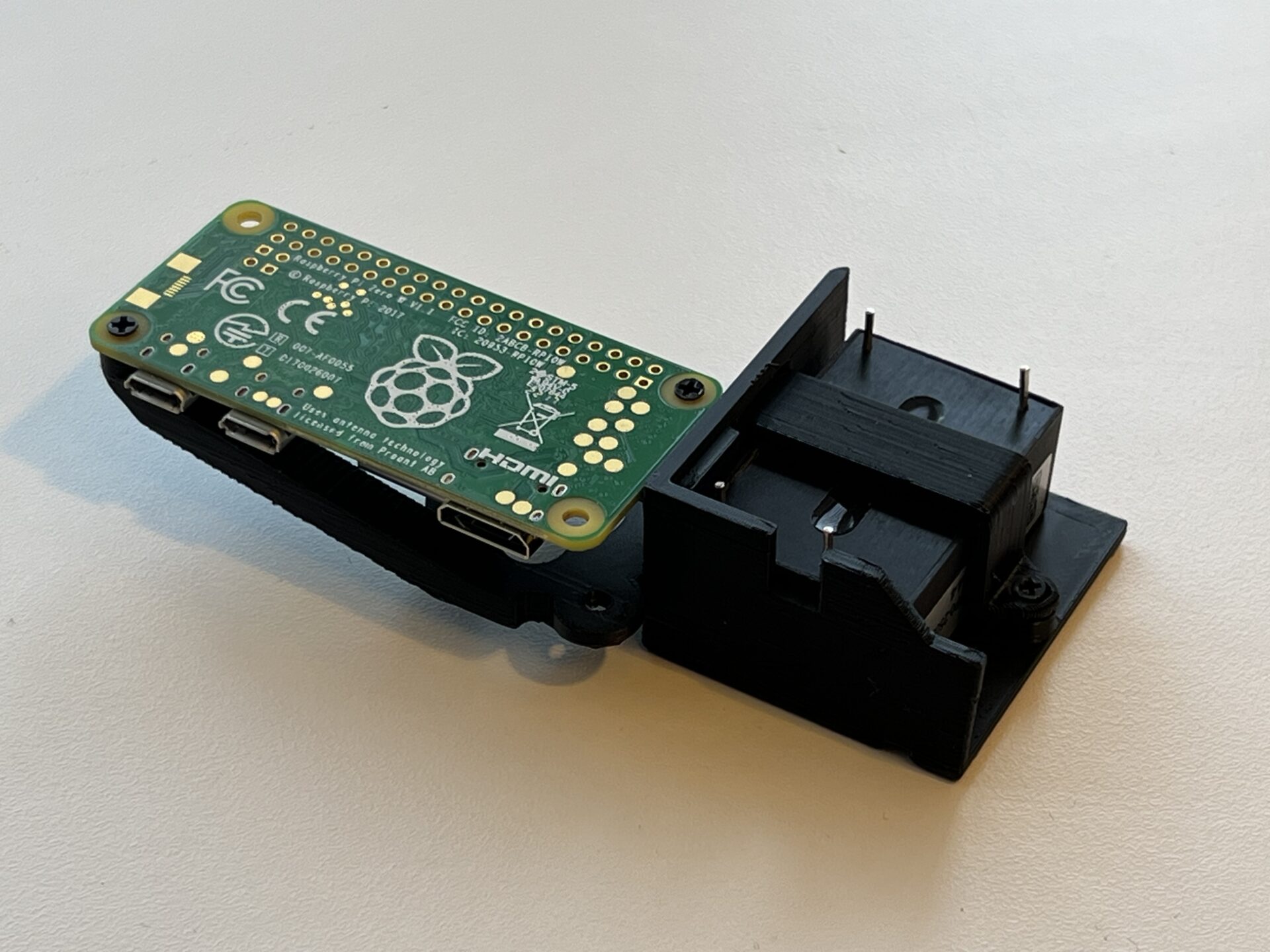
Before installation, image the micro-SD card and check it’s booting OK as it won’t be accessible once installed. True industrial cards like this SanDisk card are recommended as they will likely far outlast a cheap consumer card, and report health status (which is shown in the autostream web app).
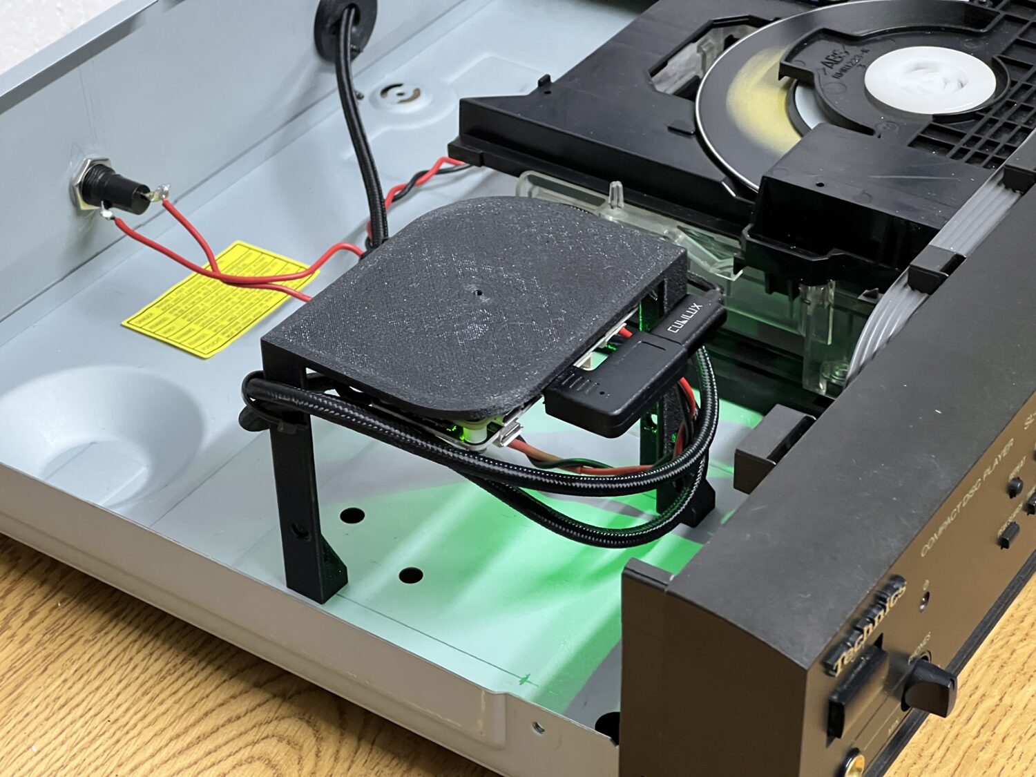
Here is the Raspberry Pi board and its power supply installed into right inside turntable:
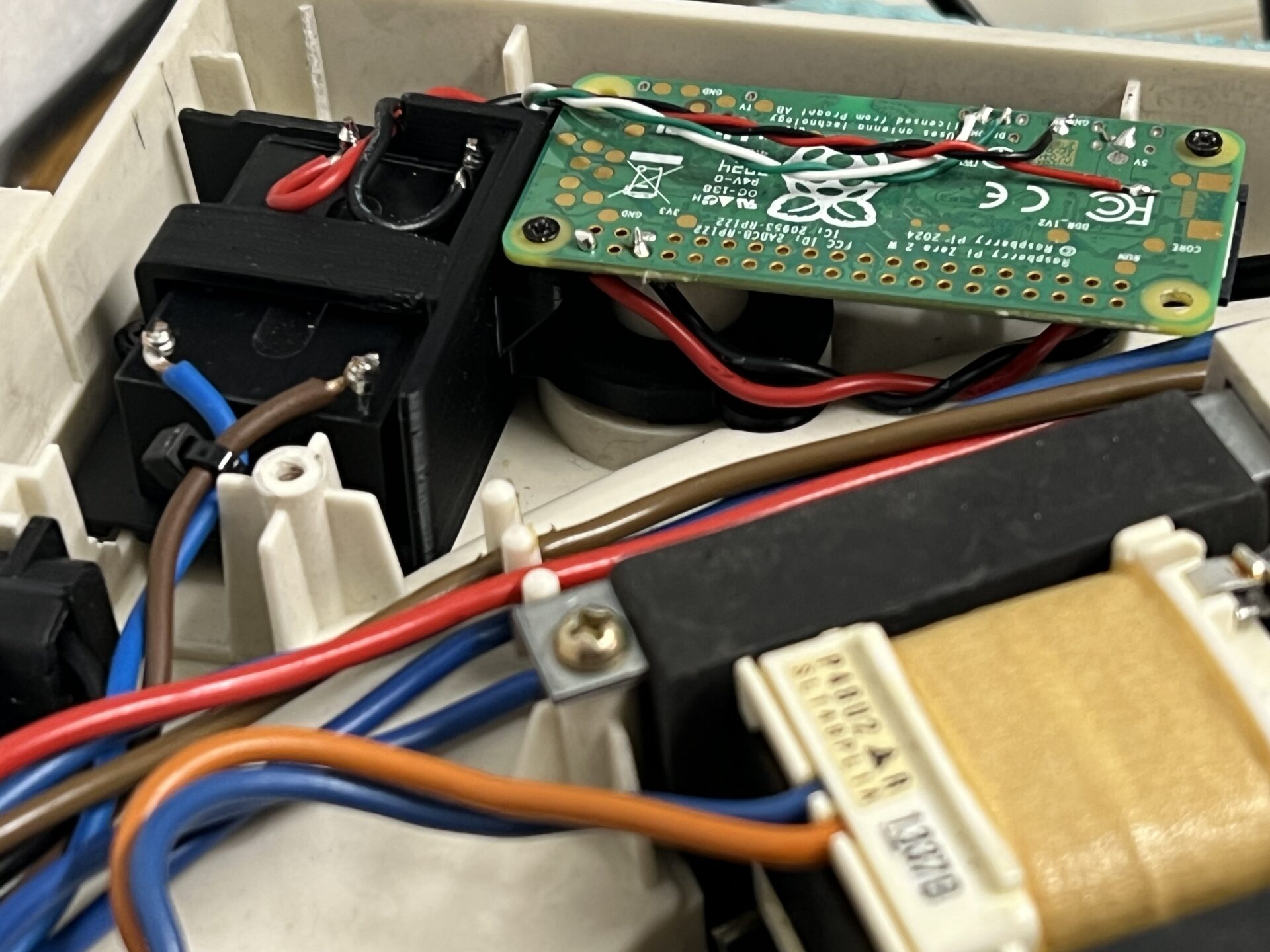
This mounting position, right at the edge of the machine, also leaves the Raspberry Pi’s Wi-Fi antenna covered only by the Technics’ ABS case. Mounted under the metal turntable platter, the signal would be greatly reduced.
Step 4: Wiring
Space inside the SL-D303 is… limited. There simply isn’t enough clearance for USB plugs; the Pi needs to be hard-wired. It conveniently provides pads for both 5V input (GPIO pads used here) and the USB connection (tiny un-labelled pads on the back).
The finished mod looks like this:
Step 5: autostream
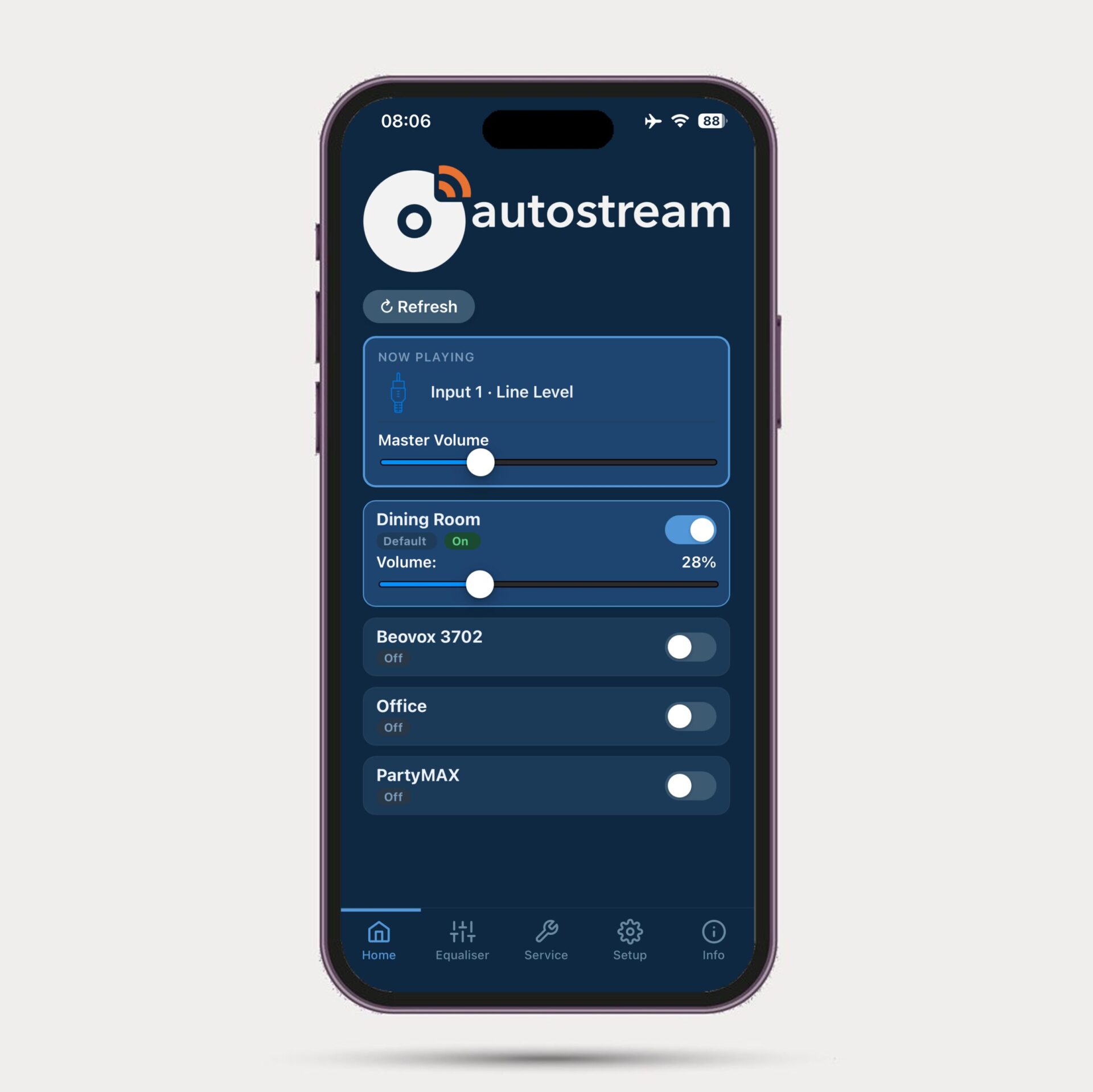
This project works because of lo-tech autostream. It uses a custom audio monitor for input and owntone for output with its own straight-forward web app to control which speakers are playing and how loud:
It also has system monitoring services that keeps the Pi running, for example by reconnecting to Wi-Fi if it drops. autostream:
- Runs headless and continuously listens for audio
- Automatically sends audio to selected AirPlay speakers
- Provides a simple mobile web interface for:
- Volume control
- Selecting which AirPlay speakers are active
- Adjusting all settings
- Provides a hotspot based WiFi setup utility if WiFi connection fails at boot (for example, if you’ve changed your router)
No manual pairing. No apps to install. No user accounts.
The User Experience
The finished result looks and behaves exactly like the original Technics design—except the sound comes out of AirPlay speakers.
A classic turntable on the outside with unmodified user interface: just press Start. In day-to-day use, it feels like the turntable was always meant to support AirPlay.
- Uses inexpensive, easily sourced hardware
- Seamless user experience: turn on, choose record, and press start – no delays, no setup, no fuss.
In Conclusion…
The goal of this project wasn’t to turn a classic turntable into a “smart device”, but to let it continue existing naturally within a modern home audio setup. Much of the joy of records is that the listening experience starts with a physical action – selecting an album.
This build lets that experience flow seamlessly into AirPlay speakers and multi-room audio without adding visible complexity or changing the character or user experience of the original equipment. The technology is invisible, leaving the focus where it belongs: on the music and the experience of playing it.
Lessons Learned
A few takeaways from this build:
- Power supply choice is critical. We need low leakage, low noise, and suitable internal protection.
- Hard-wiring the Pi dramatically improves packaging and is worth the effort.
- The UFO202 is good enough for many use-cases and autostream’s bass and treble controls give it oomph.
The obvious omission from autostream is playback start/stop from its web UI. That would in turn open up “hey Siri, play the record”. A future enhancement perhaps. It would only need a couple of components.
The other possibility is a custom PCB to use instead of the UFO202 for these Technics decks that provide a better preamp.
But either way, the if the goal is to enjoy the experience of vinyl with AirPlay with a fully automatic direct-drive turntable – something that we literally cannot buy today – this mod gets us there.
FAQ
- Can I add AirPlay to any turntable using autostream?
Yes! Many turntables available today have USB output, which can be connected directly to a Raspberry Pi tucked behind it. If you have a turntable with analogue outputs, you’ll need a USB pre-amp like the Behringer UFO202 used here. Better, more Hi-Fi oriented USB preamps are also available.
- Does this give that rich, turntable sound?
This build sounds great. There’s no hum or audible hiss, and when played through capable speakers (we have a set of converted B&O HT3702s) it’s sharp, fast, and deep – just like it should be. The autostream web app includes a six-band equaliser (with both 40Hz and 100Hz controls) to dial the sound in.
- Is there latency?
Some latency is unavoidable with AirPlay. The playback buffer can be set in autostream, and using speakers like Apple HomePods it’s possible to reduce this to about 0.5 seconds. Many speakers seem to want about 2 seconds of buffer.
- How do I install the autostream app?
The autostream software is only installed on the Raspberry Pi. On your phone, it works as a web app directly in Safari (and can be added to the home screen so it works like an app) without needing to install anything. It works entirely from the Raspberry Pi without any apps to install, cloud dependencies, or user accounts needed.
- Can this work with the SL-1210 or SL-1600?
autostream can be used with any turntable! Connect analogue sources via a USB pre-amp like used in this build, or USB capable turntables directly to the Raspberry Pi board.
- Can I used autostream without taking my Hi-Fi gear apart?
Yes! autostream runs on any quad-core Raspberry Pi board. Just put one in a readily available case, tuck it behind your Hi-Fi, and connect to your turntable. This is especially easy with USB-enabled turntables like Audio Technica’s LP60XUSB, since it’s just one wire directly from the turntable to the Raspberry Pi.
- Is the UFO202 Good Enough?
The Behringer ADC gets good reviews, but mainly because it’s cheap. But too cheap to use in a deck like this? In practice, it performs surprisingly well—and for most listening environments, likely using small AirPlay speakers, it’s definitely good enough. The autostream web app includes an equaliser if you want a slight lift in the bass and treble for example, but for many listeners using already heavily equalised AirPlay speakers, even this is unnecessary. We’ve prepared a short clip on YouTube here comparing it to a CD of the same track (listen with headphones!).
- How is this better than Bluetooth?
Using AirPlay is better than Bluetooth because it provides multi-room playback with zero pairing friction. autostream also ensures playback is completely automatic, so there’s no fiddling with phones and apps needed to just play a record. It also works with HomePods, including HomePods in stereo pairs.
Resources
- autostream project:
https://github.com/lo-tech-systems/autostream - CD Player Build (previous post):
https://www.lo-tech.co.uk/add-airplay-to-a-vintage-cd-player/ - 3D Printed Parts on Printables coming soon!