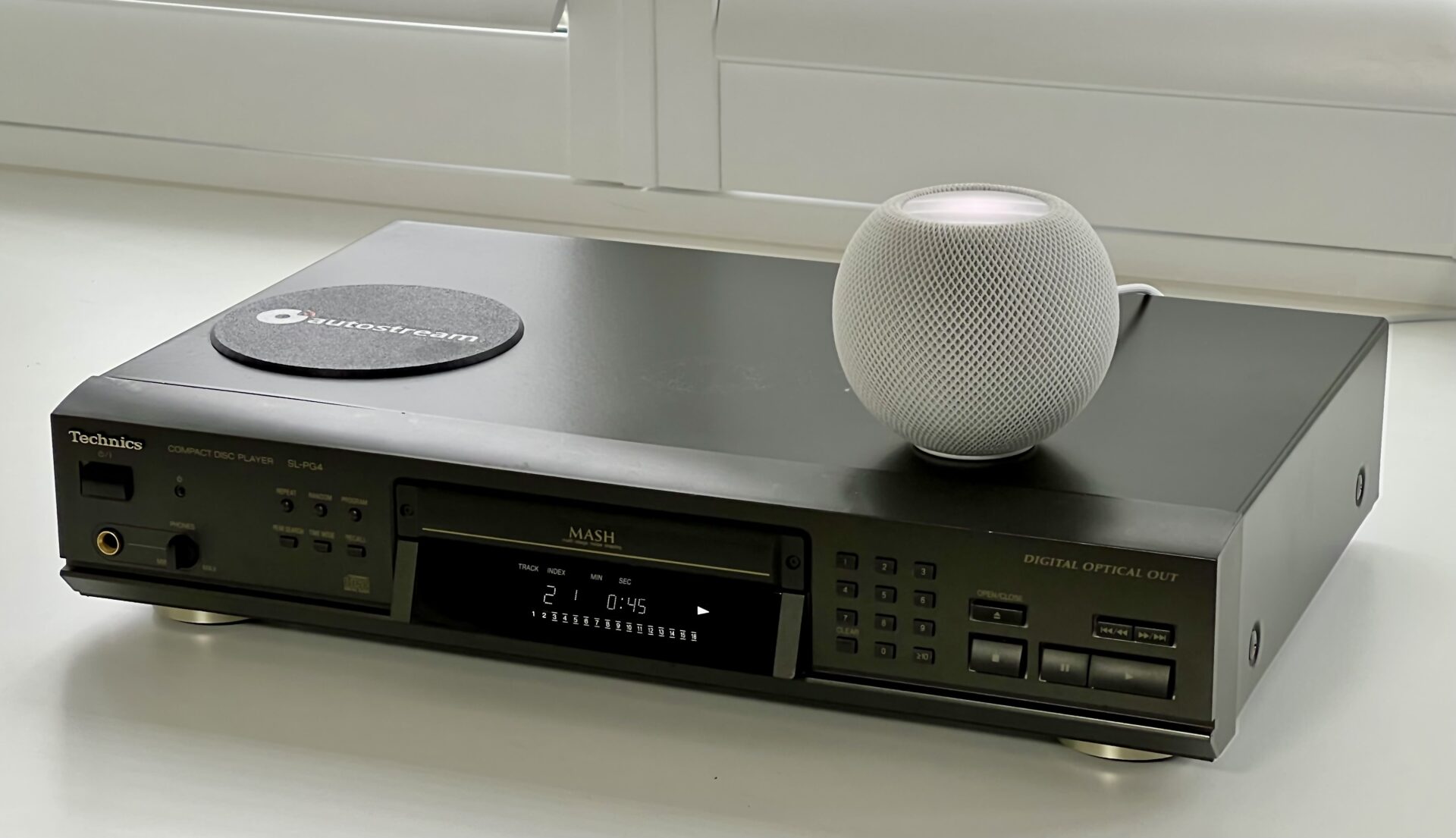
In this project, I’ll show how to convert a bog-standard CD player into a fully self-contained AirPlay CD player that “just works”. No external boxes. No fiddly startup rituals. Put in a CD, press play, and listen on your AirPlay speakers.
At the heart of the build is lo-tech autostream, which is free and available on GitHub.
- Supports AirPlay and AirPlay 2 speakers and multi-room audio
- Full digital audio with no compression
- No external boxes, old iPad’s or MacBooks
- Uses a Raspberry Pi as it’s audio streamer
- One power cable
Depending on what you have in the parts drawer, this project will cost around £40-£60.
What You’ll Need
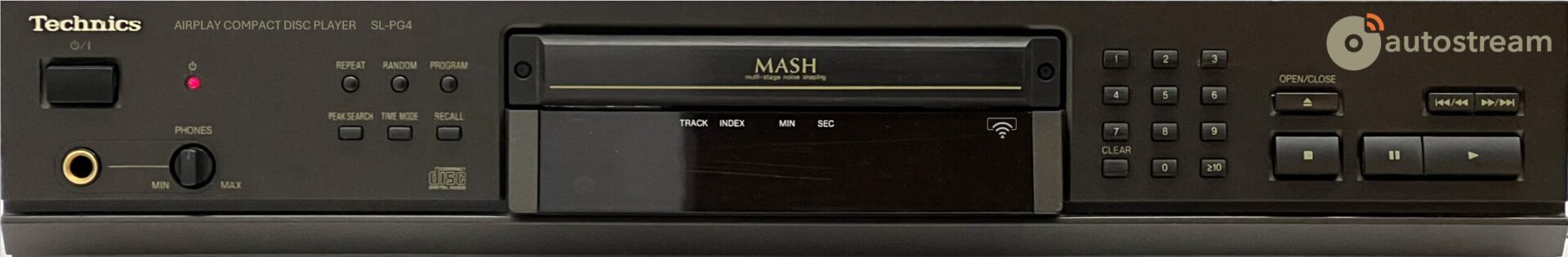
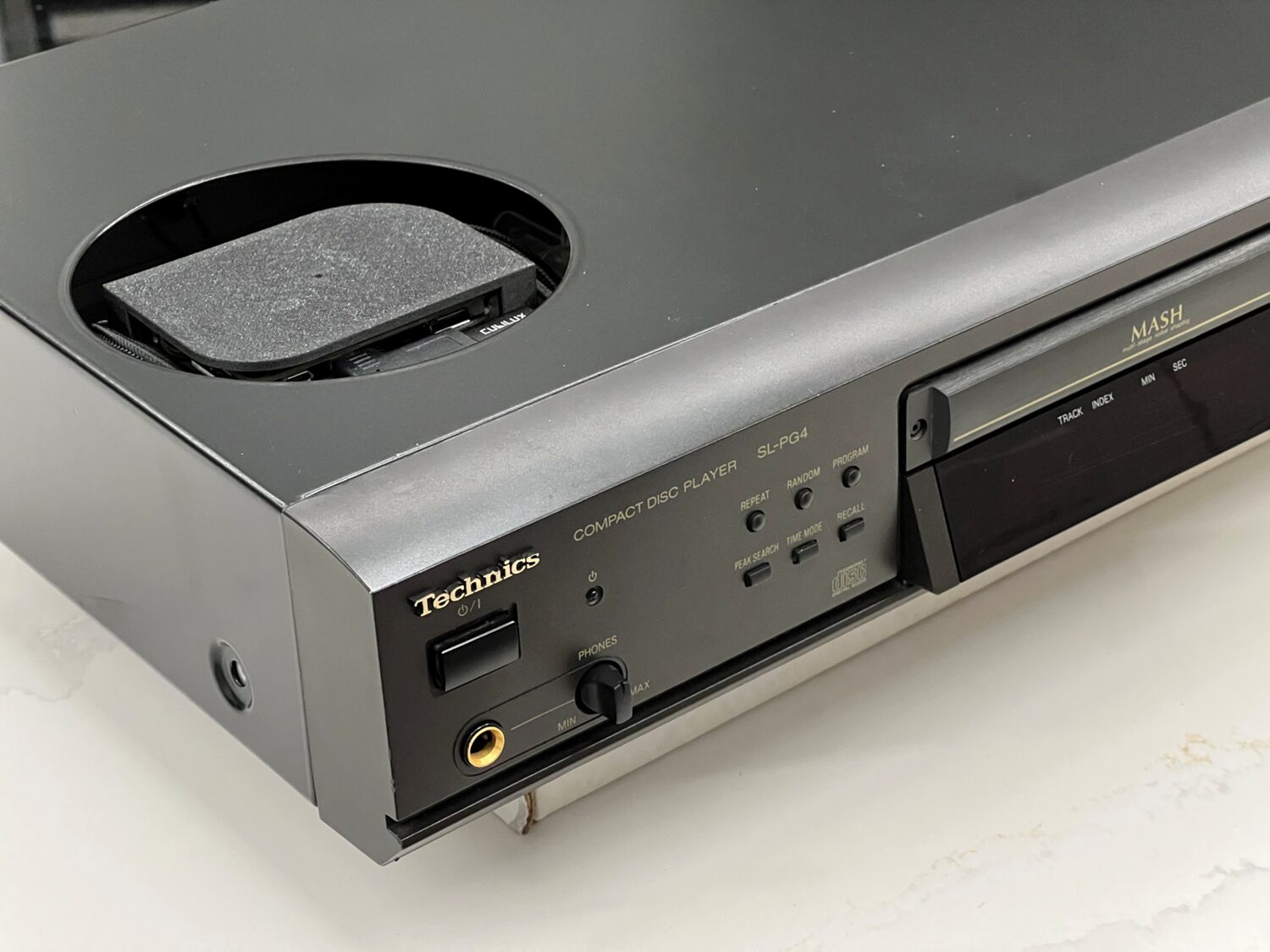
- A classic Hi-Fi CD player (Technics SL-PG4 used here)
- Raspberry Pi Zero 2W (to run autostream)
- lo-tech autostream software (free!)
- USB to SPDIF adapter
- 3D-printed mountings
- Basic hand tools & soldering equipment
Design Goals
- To work like a normal CD player: zero start-up time or setup fuss
- Embed everything within the CD player – no external boxes, dongles or power adapters
- Provide simple iPhone volume control using autostream
The result should feel like a commercial product, not a weekend hack.
Step 1: Choosing a CD Player
There are plenty of low-cost second-hand Hi-Fi CD players available on eBay. The only real requirement is that it has an optical output (and works, of course). The various early 2000s Technics players (SL-PG3/4/5) are cheap, have lots of room inside, and work great as disc transports being relatively late in CD evolution. Made in Germany too.
Since we’re connecting via optical, we’re bypassing the DACs so the audio quality will be essentially the same whatever player you choose. In some respects, the PG3 might be the best option as it lacks headphone output meaning it’s probably possible to mount the Pi right behind the plastic front panel there and avoid any external case mods.
For even lower cost, a DVD player like a Samsung DVD-HD850 will also play CDs just fine. But CD players tend to provide more room inside, offer quicker startup, and generally have more front-panel controls for functions like repeat.
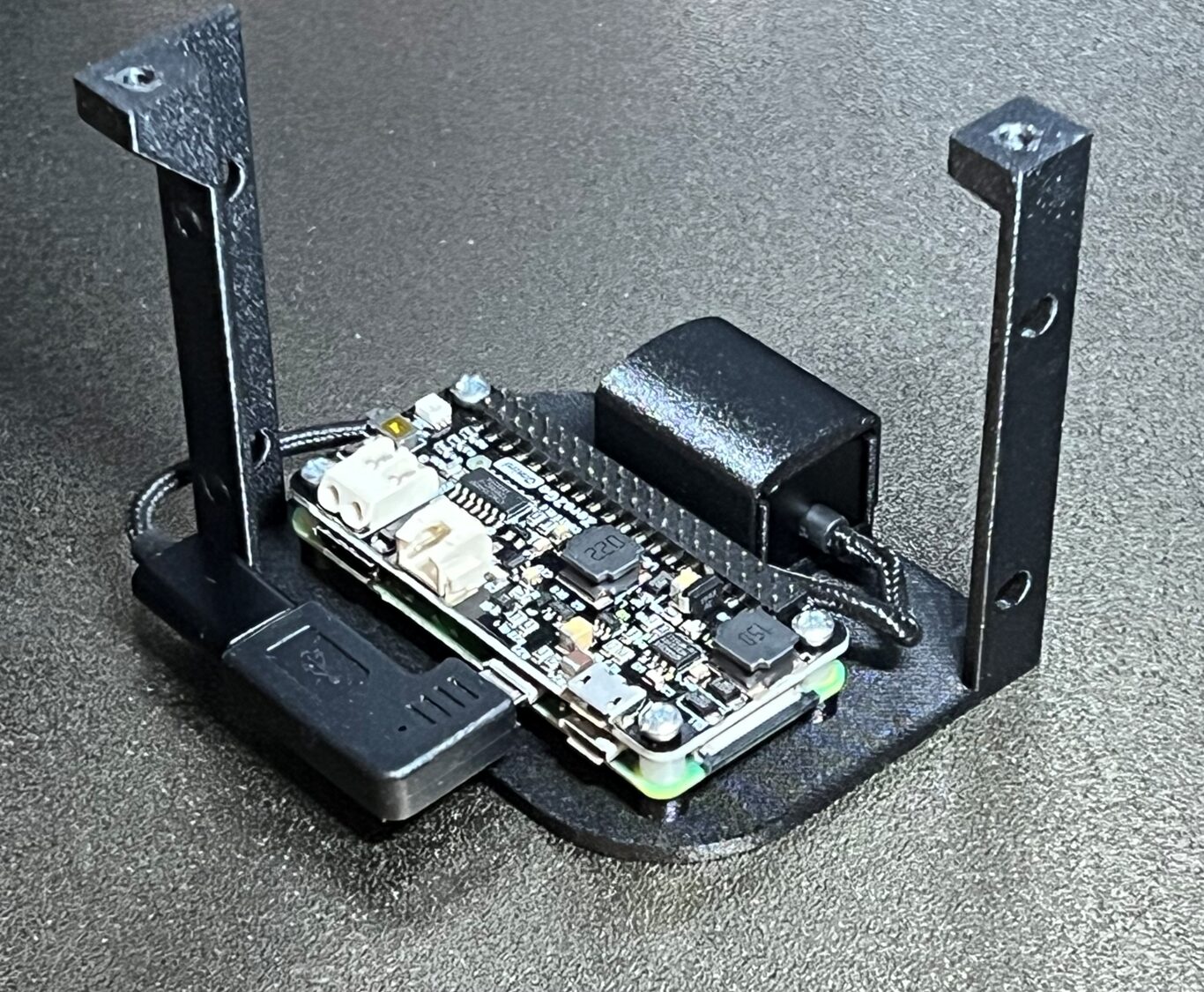
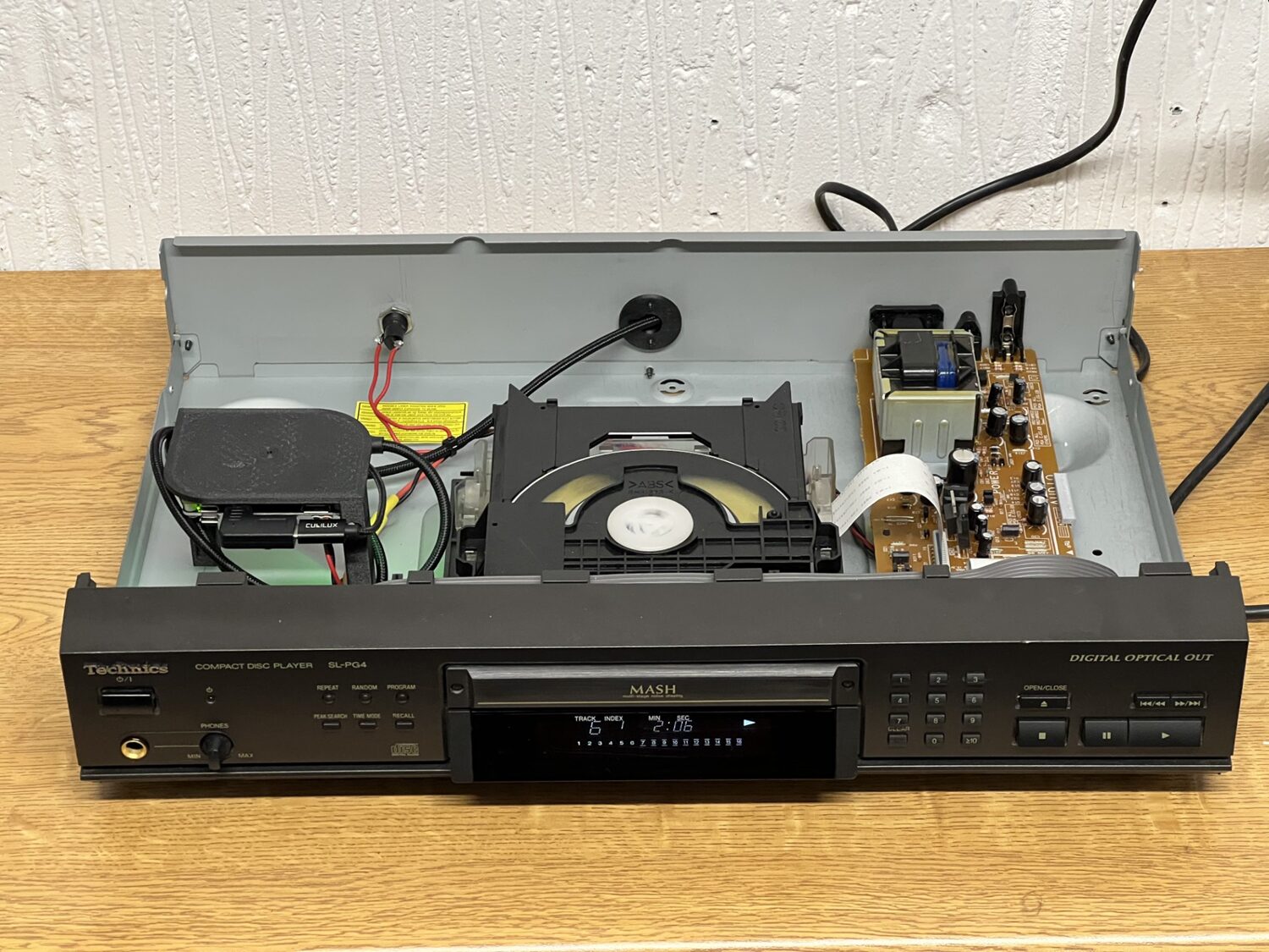
Step 2: Installing the Raspberry Pi
The Raspberry Pi Zero 2W is the ideal brain as it’s cheap, has built-in WiFi, and very low power consumption. The 3D printable bracket to mount it and a Cubilux SPDIF dongle directly in the Technics PG3/4/5 can be found on Printables here. The dongle is secured by a snap-on cap – so print it in PETG as it needs some flexibility.
This fits in the machine in what was free space:
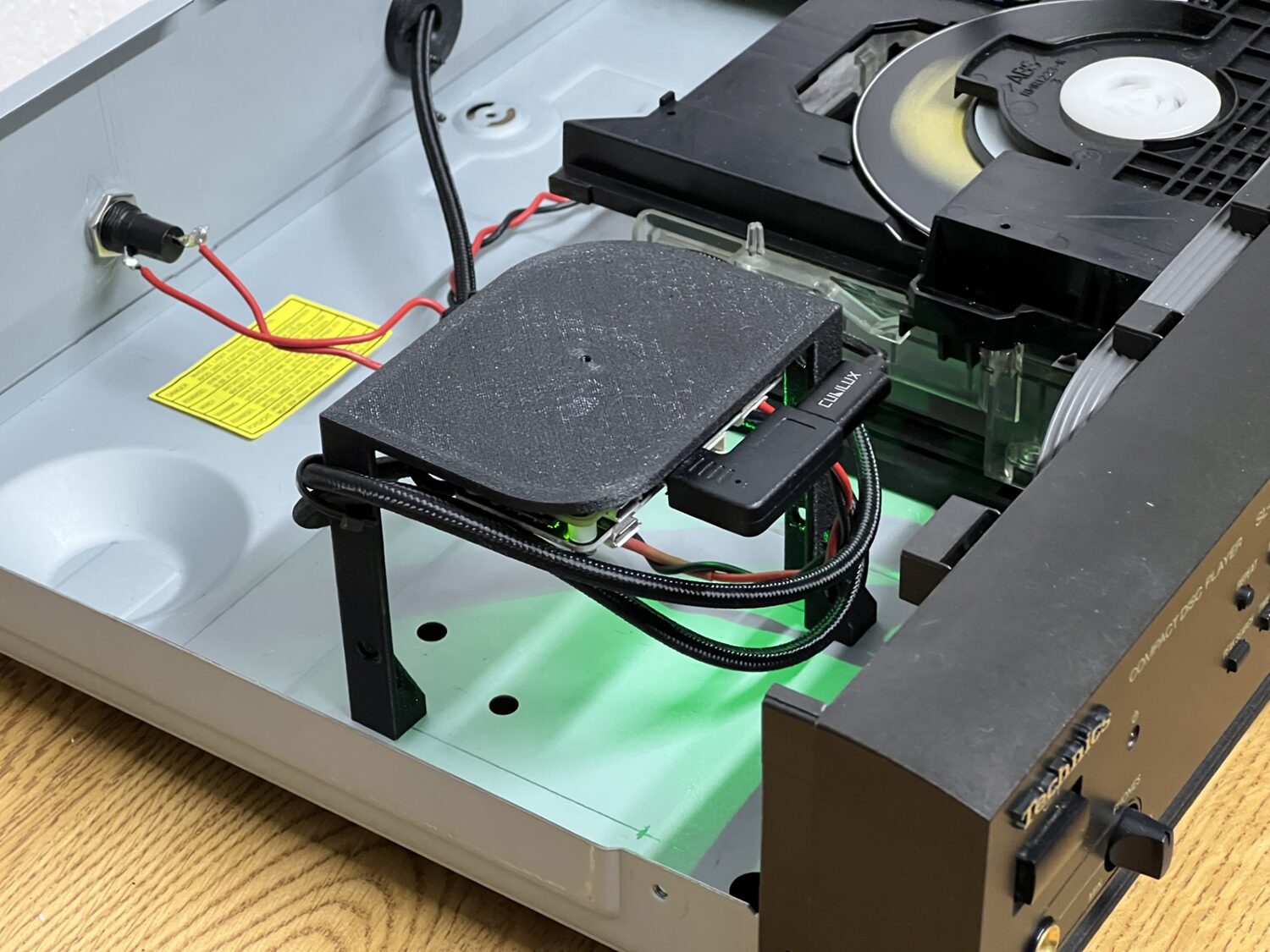
The reason for mounting the Pi near the top of the case is so that we can cut a hole (114mm hole saw) in the lid to let the WiFi signal though:
This keeps everything internal while avoiding the RF issues that come with burying Wi-Fi inside a metal box.
The Pi ZeroW will also work – but it’s very slow by comparison to any of the newer boards and more likely to cause audio glitches, for example due to RaspberryPi OS background tasks like updates.
Step 3: Powering the Pi
In short: We need about 1.5W to power the Pi Zero 2W and Technics power supply has enough headroom, avoiding the need for another power connection or transformer.
To keep the system truly self-contained, I wanted to power the Pi directly from the CD player’s internal power supply, keeping a single mains connection. With the aid of the service manual for the Technics player, the various low-voltage supplies could be easily identified:
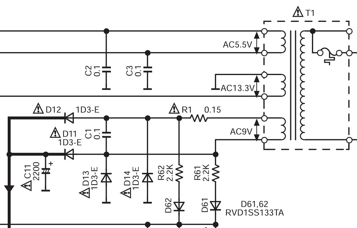
⚠️ Safety Warning: If you’re not confident working inside mains-powered equipment, stop right here and seek help or just use autostream in an external box. In any case, do not work on the mains side of the PSU – find a suitable low-voltage rail.
The Pi Zero 2W can run autostream at less than 1W average (and 1.3W peak) with some tuning – the settings to achieve this are in the wiki. Whilst the transformer output and loading are not known, feeding directly from C11’s terminals to the UU Gear Zero2Go power supply hat for the Zero doesn’t seem to add any heat to the PSU, and it’s unlikely Technics ran the player right at the PSUs limit. I’ve used a 1A ferrite bead to reduce switching noise going back into the CD player and a 500mA fuse on the back panel. The UU Gear board is ideal in this application as it allows us to connect directly to the unregulated DC supply.
The power switch on the Technics player is soft—meaning the PSU is always active. So the Pi will boot up as soon as the power is connected and be ready immediately thereafter whenever the player is turned on. With an idle power consumption of about 0.7W when waiting for music, it’s not going to get hot or run up the electricity bill either.
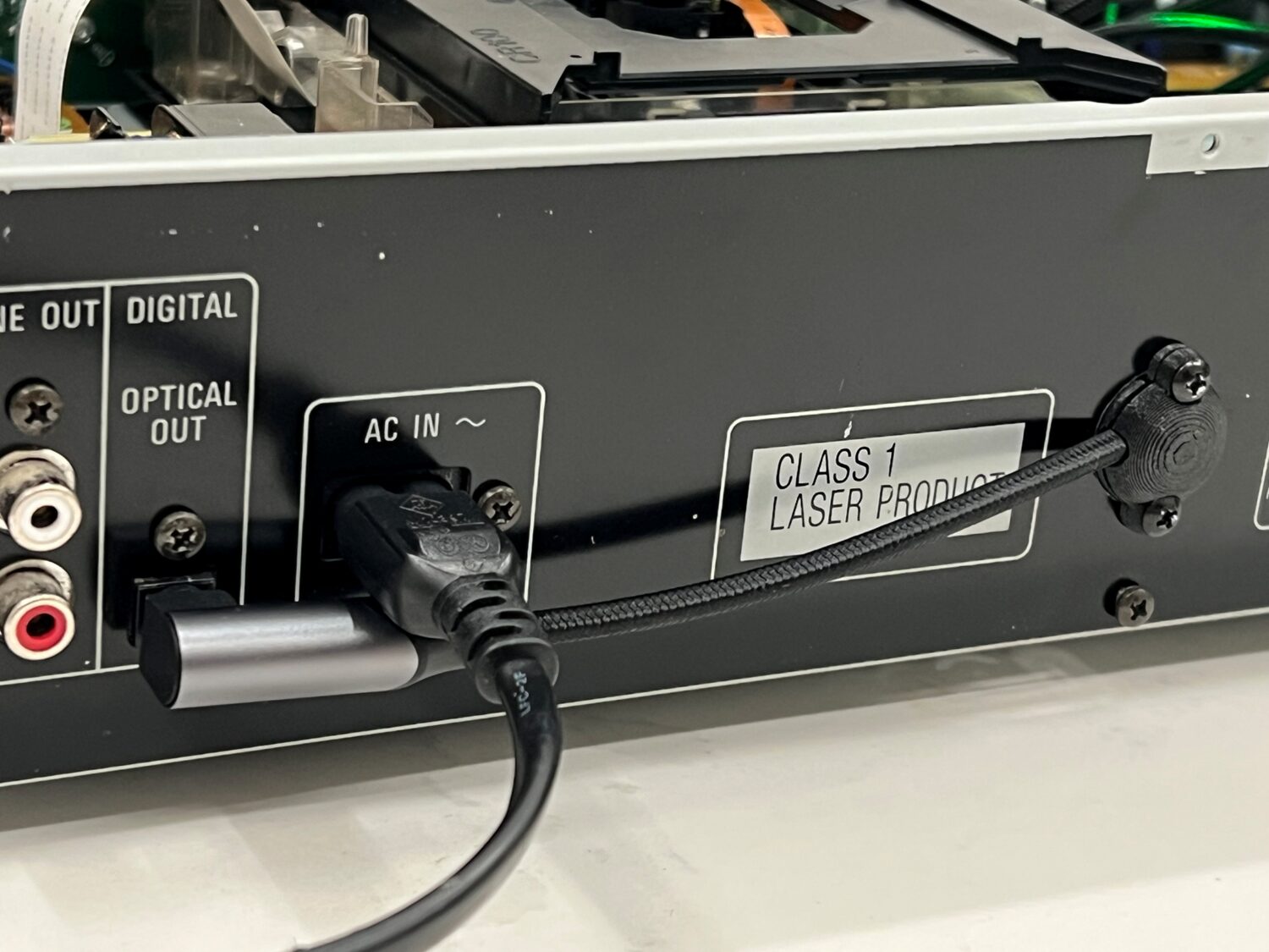
Step 4: SPDIF Digital Audio
This build keeps the signal path clean (and reversible) by using the optical output. It means we have the optical cable connected to the original port then routed straight back into the machine through a grommet. The 3D printed grommet provides a smooth curve for the right-angle SPDIF cable:
Audio Flow
- CD player outputs digital audio via optical SPDIF
- USB to SPDIF adapter presents bit-perfect digital CD data as a USB sound device
- autostream captures and sends audio via AirPlay (using Owntone)
With the SPDIF dongle mounted along side the Pi, all electronics are hidden inside the case.
Step 5: autostream
This project works because of lo-tech autostream. It’s a skin to ffmpeg (for input) and owntone (for output) with its own very simple mobile web app to control which speakers are playing and how loud:
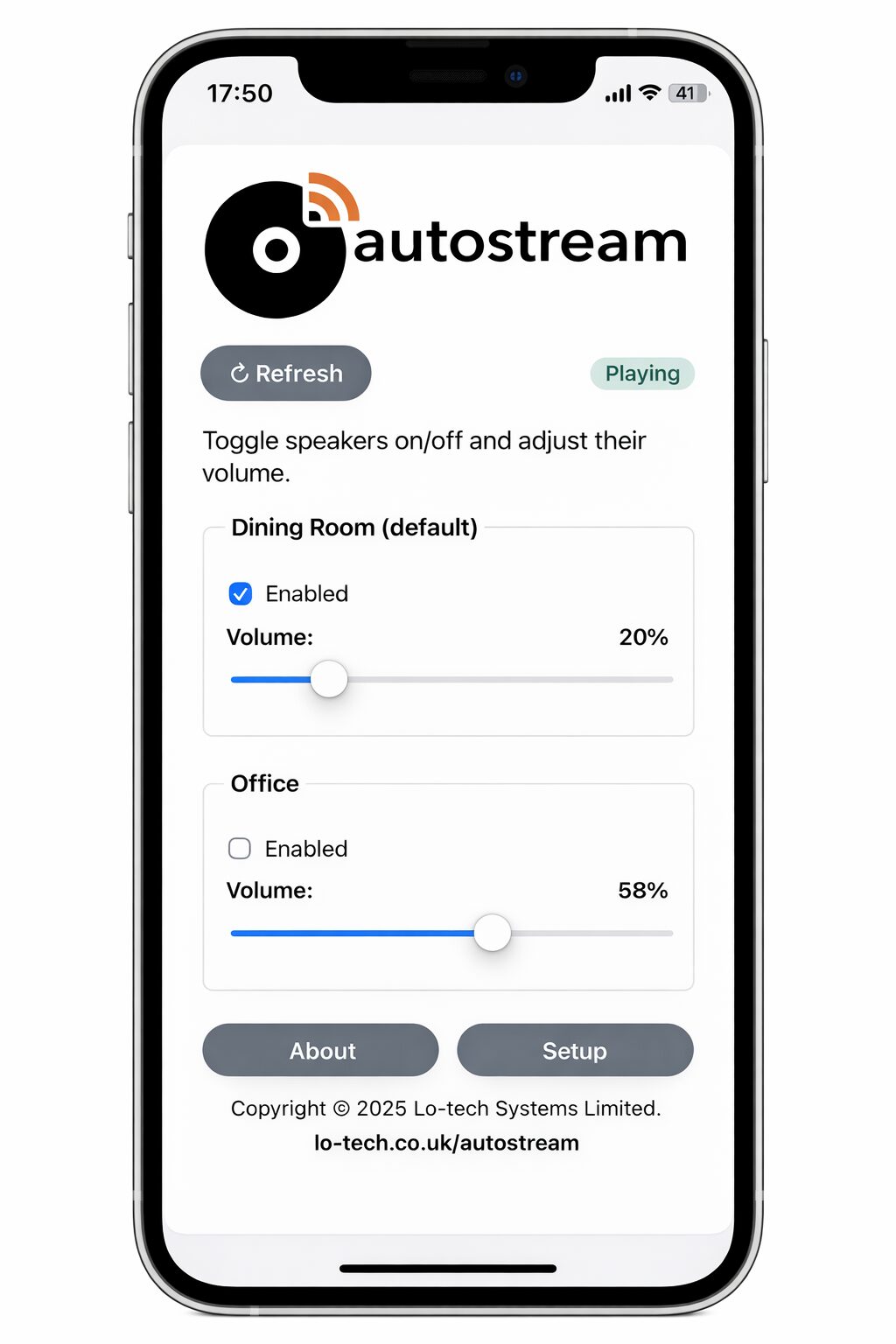
It also has system monitoring services that keeps the Pi running, for example by reconnecting to WiFi if it drops. autostream:
- Runs headless and continuously listens for audio
- Automatically sends audio to selected AirPlay speakers
- Provides a simple mobile web interface for:
- Volume control
- Selecting which AirPlay speakers are active
- Adjusting all settings
- Provides a hotspot based WiFi setup utility if WiFi connection fails at boot (for example, if you’ve changed your router)
No manual pairing. No apps to install. No user accounts.
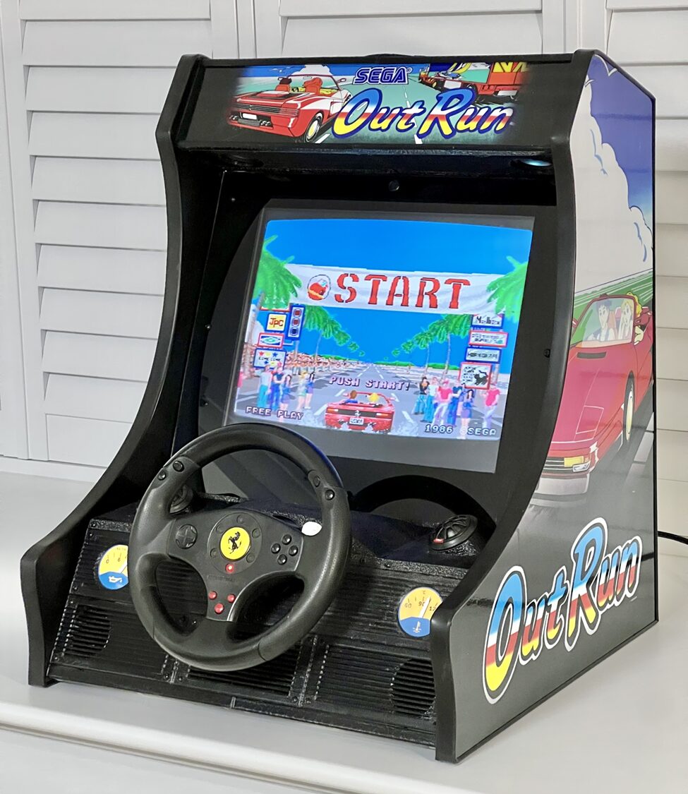
Finishing the Job
The finished result looks and behaves exactly like a normal CD player—except the sound comes out of AirPlay speakers. A classic CD player on the outside with unmodified user interface: just press play.
- In day-to-day use, it feels like the CD player was always meant to support AirPlay.
- Uses inexpensive, easily sourced hardware (some of which you may already have)
- Preserves the original CD player functionality
- Works entirely in the digital domain and so preserves CD quality
- Leverages autostream’s always-on design
- Could easily be used for other Hi-Fi components—most obviously record players.
In Conclusion…
I realised that I missed my old CDs. Maybe I just quite liked the 90s.
Thanks to owntone providing the AirPlay output and Technics thoughtfully providing their CD players with always-on PSUs and loads of space inside them, this project exactly preserves the way the CD player worked and adds multi-room WiFi streaming.
autostream turns old Hi-Fi equipment into something that fits naturally into a modern, multi-room setup, without changing how we interact with it at all. Perhaps, the player Technics would make now.