The first in a series of four posts covers a 12‑year journey to build a home-brew OutRun cab which feels, to me, like the arcade. Find this project, including a ready-to-run Windows build, on GitHub.
Some things from childhood just stick. The smell of an electronics shop. The lights and noise of an arcade on a wet winter afternoon. That feeling when you realise you’ve deleted your Dad’s work trying to install Doom on the family computer.
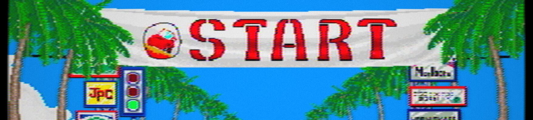
For me, playing OutRun (randomly, on the QE2) was such a thing. The colours, that sound track, and of course, the sense of speed; it was like nothing else at the time. I spent maybe an hour on it. But that shimmering start line, the haloed edges of palm trees in their shadows, and the difficulty seeing over the hill crests hold clear in my mind.
But memories aren’t always accurate. The way I think the game looked isn’t quite the way it really did. We didn’t have 4k graphics as a reference point. Our imagination did the HD upscaling through the haze.
When Chris White released his brilliant open-source re-implementation, CannonBall, the game was no longer locked inside the dusty arcade board in my “in-need-of-repair drawer”, the eternally enthusiastic start line crowd presumably awaiting another pound coin that would never come. It provided a way to test my memory against reality — and maybe to rebuild the version that lived in my head.
A Slow-Burn Side Project
It would need a cabinet and a wheel. A home-made bartop. I didn’t know it would take me 12 years, but I did know I’d never be happy looking at it on an LCD screen. So I set about modifying it and eventually ended up with this:
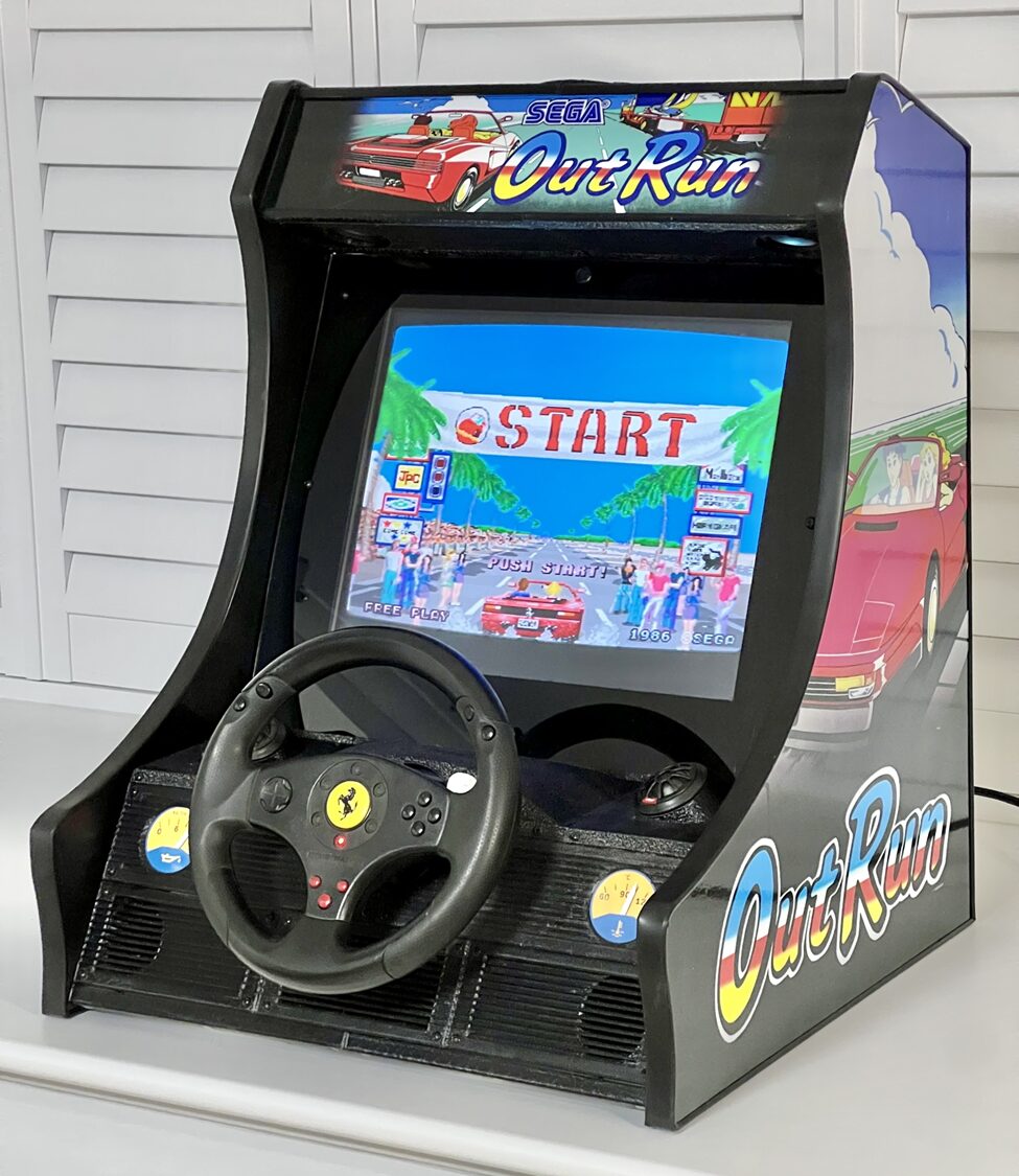
The goal was simple — make OutRun feel right, and have it running on a (new at the time) Raspberry Pi. The original arcade hardware used a high-quality RGB system, but even so the CRT screens blurred, blended and desaturated the image in a way that encouraged our minds to fill in the gaps. LCDs take that away, and we’re left with the stark reality of a 320×224 image. The challenge was capturing the feel of the arcade screen, without needing massive processing power.
A true back-burner project, picked up and put down over twelve years. Which gave time to stumble on bugs in the arcade code along the way. Did anyone ever notice that the game count-down and stage timers didn’t count seconds on the same basis I wonder.
What started as trying to modify the game to use the Blargg NTSC filter library, something I’d read about some years previous, soon became a deep dive into areas new to me: SDL, GLSL shaders, multi-threading, the intricacies of 1980s video signal handling, and latterly, 3D printing (of the cabinet dashboard).
Re-Capturing the Analogue Soul
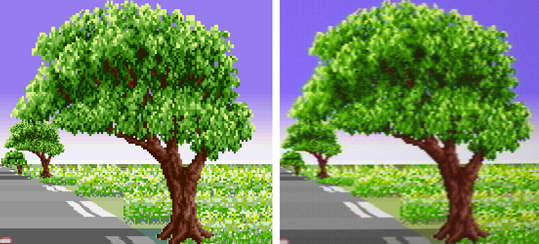
Actually adding the NTSC filter produced immediately satisfying results. It also ran a 7fps. But the concept seemed like it should work, scenery suddenly looking more believable:
Viewed at close range, CRTs are full of dots caused by the shadow mask. It was obvious some kind of emulation was needed, but simulating the mask or adding scan lines just decimated brightness. At least the arrival of the Pi2 whilst I pondered had lifted the frame rate a bit.
Performance continued to trouble me. The Raspberry Pi could easily play full-screen video, but took ages to do basic tasks like compile anything. It’s because it’s mostly GPU, a small CPU strapped on the side almost as an afterthought. Video plays well because the tiny ARM core isn’t really involved.
So I needed to learn how to use the GPU – the subject of the next post. But I’d settled on my approach and felt it should be possible to get it all to run at 60fps. Oh, and acquired some wood.
Behind the cabinet plexiglass, the end result is surprisingly effective at creating the impression a real CRT is within, producing an image that feels closer to memory than to mathematics. In motion it’s even better, with the soft shimmer in the trees.
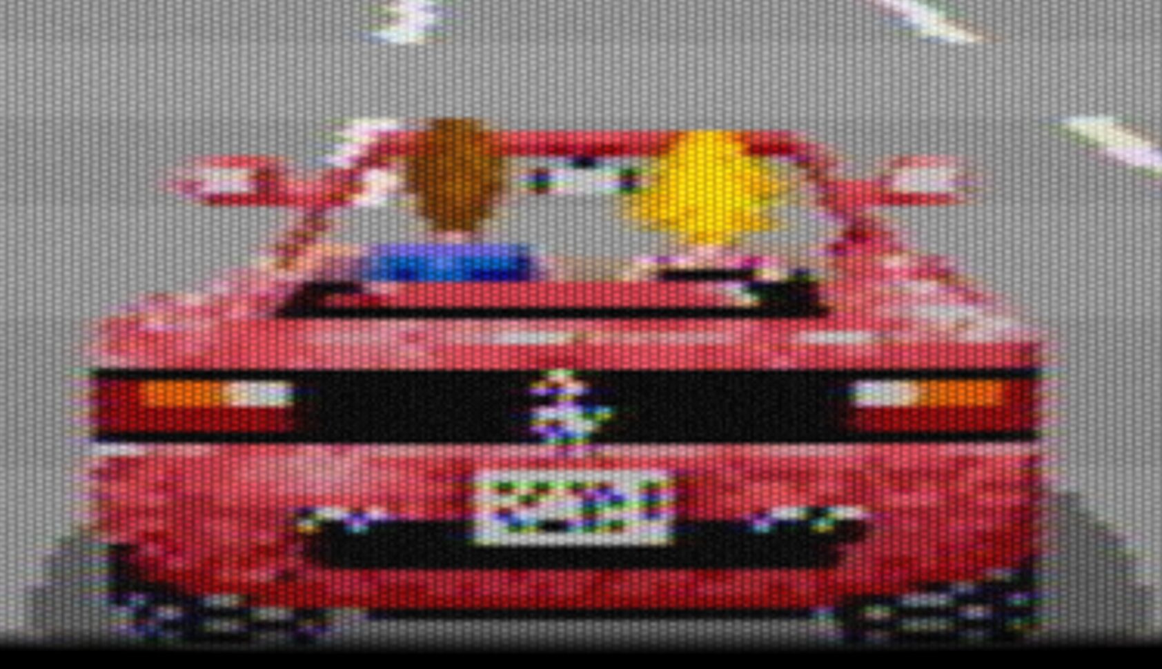
Zoomed in 5x, we can see what the processing is doing. The combination of filter to soften the image and non-linear mask overlay that preserves highlight brightness just kind-of works. Visuals sorted.
More than Video
OutRun wasn’t just about visuals — the music and sound are instantly recognisable to a anyone born in the 70s. My heavy video processing, though, left the music stuttering and laggy. So I’ve rewritten the audio engine to run smoothly even on the most basic Raspberry Pi boards, using threading to stay consistent under load. And added MP3 playback; who hasn’t wanted to race away from the line to A-ha’s Take On Me? The audio system will be the subject of a future post.
But the foundation remains Chris White’s truly outstanding work — a meticulous de-compilation of the original. CannonBall-SE builds on it, making what I wanted for my bartop. After twelve years, it finally feels right. Not exactly how it was, but how I remember it; perhaps the only version that really matters.
Coming Soon: CannonBall-SE: The Shaders.
If you’d like to try CannonBall-SE, you can grab the Windows executable and source from GitHub. Installing on RaspberryPi boards is super easy too — clone the repo and run ./install.sh, which automatically installs dependencies and compiles the game in about 5 minutes on a Pi3.
👉 https://github.com/J1mbo/CannonBall-SE
CannonBall-SE is a personal project that I hope will be of interest to vintage computing enthusiasts.
Important: CannonBall-SE is an open-source engine that requires original OutRun ROMs from a legally sourced PCB to function. This project is not affiliated with or endorsed by SEGA. OutRun is a registered trademark of SEGA. This software is provided for educational and preservation purposes only.