
The XT-CFv3 DMA transfer mode works in an unconventional way to deliver the highest possible throughput for the original IBM PC and PC/XT – here’s how.
The Intel 8237 DMA Controller
In the PC and PC/XT, the Intel 8237 DMA controller provides two functions – it keeps system memory alive by periodic refresh, and it enables transfers to and from IO devices with minimal CPU intervention (the floppy drive, many hard disk controllers, and SoundBlaster cards use DMA). To achieve this, the DMA controller has four sets of DMA Request (DRQ) and DMA Acknowledge (DACK) lines and broadly, the process is:
- DRQ is asserted by the requesting IO device (e.g. the floppy drive controller)
- The DMA controller raises the HOLD line (connected to the 8088 CPU)
- The 8088 CPU completes the current bus cycle, then asserts HLDA (Hold Acknowledge) so passing control to the DMA controller. At this point, all output lines on the CPU are put in a high-Z state (effectively disconnected) and the CPU enters a waiting state
- Now the DMA controller has control of the bus, it presents the memory address on the address bus and asserts AEN, which signals to IO devices not involved in the DMA transfer to disregard the bus cycle
- The DMA controller next asserts DACK, preparing the IO device to present (or receive) data
- Then the DMA controller asserts both IOR (IO read) and MEMW (memory write) concurrently, or IOW (IO write) and MEMR (memory read), so feeding data directly from the device to memory or vice-versa
- The DMA controller transfer counter and memory address registers are then updated
What happens next depends on whether more data is available (so DRQ is still asserted), whether the transfer counter has reached zero, and finally the DMA controller operating mode. In single byte transfer mode, the DMA controller will return control to the CPU by releasing HOLD after each byte, whilst in demand mode the process will continue until the IO device releases DRQ (block mode generally isn’t used because it can disrupt RAM refresh, as described below).
DMA vs Port IO
In demand mode DMA runs much faster than 8088/V20 transfers since with DMA, each byte is delivered to memory in just one bus cycle. The 8088, on the other hand, has to read the byte from the IO device in one bus cycle then store it to memory in a second bus cycle, because both the IO device and memory use the same address bus. On the 8088, the code to fetch a block of port mapped data is less than ideal:
mov cx, 512
 .TransferLoop:
 in al, dx
 stosb
 loop .TransferLoop
The instruction fetch and jumps of course make this slow, although it can be improved by unrolling. In the XTIDE Universal BIOS, this is the basis of the 8-bit port-mapped IO operating mode for the XT-CF series, achieving about 170KB/s at 4.77MHz. The V20 though streamlines this by eliminating instruction fetch and jump overhead:
mov cx, 512
 rep insb
Freeing up the bus for just the data by the elimination of all the instructions pays significant dividends – this delivers about 390KB/s at 4.77MHz (and is available in the ‘XTplus’ XTIDE Universal BIOS build, for V20/286 powered XT class hardware).
Making DMA Scream
DMA on the PC and PC/XT brings with it some challenges:
- Programming the DMA controller absorbs many cycles
- Control must be returned to the CPU every 15 µs (72 cycles) for RAM refresh
- To play sampled SoundBlaster audio at 22KHz, the DMA controller must be available to service the SoundBlaster DRQ once every 216 cycles
For my goal of ultimate throughput, packing bytes back-to-back on the data bus is the key – and with each byte taking 4 cycles, 18 bytes can be transferred before disrupting RAM refresh. For the XT-CFv3, this is achieved with some counter logic to release DRQ after 16 bytes (since that makes the maths easy and provides a margin of safety):
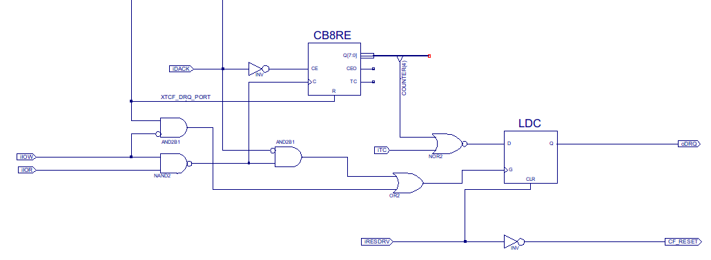
In the XT-CFv3, the oDRQ output in the schematic is delivered to the ISA bus via a 3-state output buffer, because the card must be able to co-exist with any original hard disk controller and DMA channels (DRQ/DACK pairs) can’t be shared as there are no pull-ups on the DRQ lines, so the card must drive the line continually when DMA function is in use.
Generating DRQ
Because DRQ is released by the counter, the DRQ lines on the IDE interface can’t be used – and in any case, DMA isn’t even supported by the majority of CompactFlash cards. The XT-CFv3 therefore provides another mechanism – to allow the software direct control over DRQ through an IO port write (the address decoding for which appears in the schematic above as ‘XTCF_DRQ_PORT’). This approach makes the transfer code itself elegant, once the DMA controller has been programmed:
mov cx, 32
 .TransferNextDmaBlock:
 out        dx, al                ; Raise XT-CFv3 DRQ & transfer 16 bytes
 loop    .TransferNextDmaBlock    ; loop also adds required wait-state
The results are heavily dependent on the media: the majority of CompactFlash cards support only single-sector transfers, and therefore the DMA controller must be programmed once for every 512 bytes transferred, which delivers about 420 KB/s – a vast improvement on 8-bit port IO. But for devices supporting multi-sector transfers, performance rises to 530KB/s with an 8088 and a 560KB/s with a V20 (both at 4.77MHz).
More Information
- There’s a great section on the IBM PC DMA system architecture in the Mindshare book, “ISA System Architecture”, the 3rd edition of which is available for purchase as an eBook directly from Mindshare
- Lo-tech XT-CF Boards
I’d like to add another advantage of DMA over port I/O rather than just the speed:
DMA transfers occur ‘in the background’, so your CPU can still perform other tasks.
This allows things like smooth streaming of audio/video such as in demos like 8088 Corruption and 8088 Domination.
With port I/O the CPU is locked up during the entire transfer.
The early harddisk controllers that IBM used in the 5160 were doing DMA transfers as well.
That is true for demand mode generally, however in this case the XT-CFv3 logic completely saturates the bus by design meaning that the CPU would be in a hold state completely. The BIOS code as it stands also just uses the DMA as a fast sector transfer.
Yes, if the disk is fast enough. In the case of the original disks used on 5160 systems, they weren’t. They’d do about 90 kb/s tops.
I’m not sure what the slowest IDE drive would be, but I would think that some early drives would not be able to saturate a 5160 bus. They probably did in the range of 200-300 kb/s?
Correct, this card is abusing the bus based on the capabilities of CompactFlash 🙂
The problem with DMA is that the CPU can’t do anything while a DMA transfer is happening. At least not with vintage system designs.
Whilst true, the motivation for looking to DMA with the XT-CFv2 was to increase the transfer rate as much as possible.