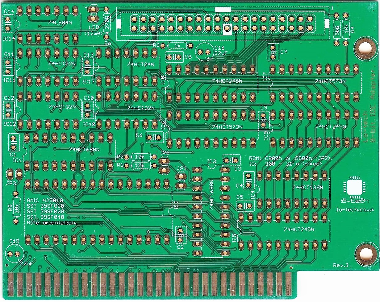
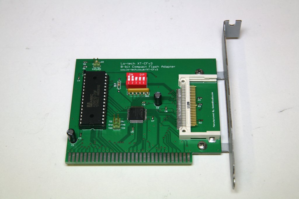
The Lo-tech 8-bit IDE adapter has been designed around a 3D-printed ISA slot bracket, the primary reason being to keep the card itself within a 100mm width, which helps keep the price down. Until now!
Announcing then the rev.3 board, which is now compatible with the Keystone 9202 ISA slot bracket, as available from the usual online electronics retailers such as Mouser.
As well as the slightly larger PCB form factor, this version also includes another jumper (JP3) providing a choice of IO ports, either the default 300h or 320h.
The board keeps everything else the same – XTIDE Universal BIOS powered, 32KB Flash ROM, excellent IDE and SATA device compatibility, high-speed read and write performance, key-pin power for Disk On Module devices, and PC/XT Slot-8 compatibility (with option SMT components fitted).
The XT-CFv3 DMA transfer mode works in an unconventional way to deliver the highest possible throughput for the original IBM PC and PC/XT – here’s how.
The Intel 8237 DMA Controller
In the PC and PC/XT, the Intel 8237 DMA controller provides two functions – it keeps system memory alive by periodic refresh, and it enables transfers to and from IO devices with minimal CPU intervention (the floppy drive, many hard disk controllers, and SoundBlaster cards use DMA). To achieve this, the DMA controller has four sets of DMA Request (DRQ) and DMA Acknowledge (DACK) lines and broadly, the process is:
DRQ is asserted by the requesting IO device (e.g. the floppy drive controller)
The DMA controller raises the HOLD line (connected to the 8088 CPU)
The 8088 CPU completes the current bus cycle, then asserts HLDA (Hold Acknowledge) so passing control to the DMA controller. At this point, all output lines on the CPU are put in a high-Z state (effectively disconnected) and the CPU enters a waiting state
Now the DMA controller has control of the bus, it presents the memory address on the address bus and asserts AEN, which signals to IO devices not involved in the DMA transfer to disregard the bus cycle
The DMA controller next asserts DACK, preparing the IO device to present (or receive) data
Then the DMA controller asserts both IOR (IO read) and MEMW (memory write) concurrently, or IOW (IO write) and MEMR (memory read), so feeding data directly from the device to memory or vice-versa
The DMA controller transfer counter and memory address registers are then updated
What happens next depends on whether more data is available (so DRQ is still asserted), whether the transfer counter has reached zero, and finally the DMA controller operating mode. In single byte transfer mode, the DMA controller will return control to the CPU by releasing HOLD after each byte, whilst in demand mode the process will continue until the IO device releases DRQ (block mode generally isn’t used because it can disrupt RAM refresh, as described below).
DMA vs Port IO
In demand mode DMA runs much faster than 8088/V20 transfers since with DMA, each byte is delivered to memory in just one bus cycle. The 8088, on the other hand, has to read the byte from the IO device in one bus cycle then store it to memory in a second bus cycle, because both the IO device and memory use the same address bus. On the 8088, the code to fetch a block of port mapped data is less than ideal:
mov cx, 512
 .TransferLoop:
 in al, dx
 stosb
 loop .TransferLoop
The instruction fetch and jumps of course make this slow, although it can be improved by unrolling. In the XTIDE Universal BIOS, this is the basis of the 8-bit port-mapped IO operating mode for the XT-CF series, achieving about 170KB/s at 4.77MHz. The V20 though streamlines this by eliminating instruction fetch and jump overhead:
mov cx, 512
 rep insb
Freeing up the bus for just the data by the elimination of all the instructions pays significant dividends – this delivers about 390KB/s at 4.77MHz (and is available in the ‘XTplus’ XTIDE Universal BIOS build, for V20/286 powered XT class hardware).
Making DMA Scream
DMA on the PC and PC/XT brings with it some challenges:
Programming the DMA controller absorbs many cycles
Control must be returned to the CPU every 15 µs (72 cycles) for RAM refresh
To play sampled SoundBlaster audio at 22KHz, the DMA controller must be available to service the SoundBlaster DRQ once every 216 cycles
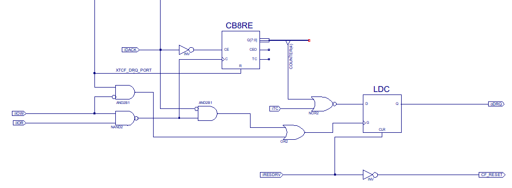
For my goal of ultimate throughput, packing bytes back-to-back on the data bus is the key – and with each byte taking 4 cycles, 18 bytes can be transferred before disrupting RAM refresh. For the XT-CFv3, this is achieved with some counter logic to release DRQ after 16 bytes (since that makes the maths easy and provides a margin of safety):
In the XT-CFv3, the oDRQ output in the schematic is delivered to the ISA bus via a 3-state output buffer, because the card must be able to co-exist with any original hard disk controller and DMA channels (DRQ/DACK pairs) can’t be shared as there are no pull-ups on the DRQ lines, so the card must drive the line continually when DMA function is in use.
Generating DRQ
Because DRQ is released by the counter, the DRQ lines on the IDE interface can’t be used – and in any case, DMA isn’t even supported by the majority of CompactFlash cards. The XT-CFv3 therefore provides another mechanism – to allow the software direct control over DRQ through an IO port write (the address decoding for which appears in the schematic above as ‘XTCF_DRQ_PORT’). This approach makes the transfer code itself elegant, once the DMA controller has been programmed:
mov cx, 32
 .TransferNextDmaBlock:
 out        dx, al                ; Raise XT-CFv3 DRQ & transfer 16 bytes
 loop    .TransferNextDmaBlock    ; loop also adds required wait-state
The results are heavily dependent on the media: the majority of CompactFlash cards support only single-sector transfers, and therefore the DMA controller must be programmed once for every 512 bytes transferred, which delivers about 420 KB/s – a vast improvement on 8-bit port IO. But for devices supporting multi-sector transfers, performance rises to 530KB/s with an 8088 and a 560KB/s with a V20 (both at 4.77MHz).
Since working on the Dangerous Prototypes version of the XT/IDE project, I’ve been increasingly interested in ‘the storage problem’ for early 1980’s PCs – it’s both difficult to transfer files between machines and increasingly problematic storing data on them too, with still surviving hard drives now well into borrowed time.
The goal was to make a board with the DMA function of the XT-CFv2, but as easy to make as the XT-CF-lite (only the CompactFlash header represents something of a soldering challenge). So the XT-CFv3 specs:
8-bit ISA card providing bootable fixed-disk storage for PC/XT and PC/AT class hardware
Up to 8GB usable by MS-DOS (DOS limit)
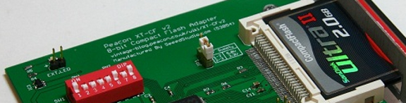
CompactFlash header positioned to allow CompactFlash media to be exchanged through a custom ISA card slot, without opening the PC
32KB in-system re-programmable flash ROM, providing storage for the XTIDE Universal BIOS boot ROM with 24KB free
Provides several transfer modes optimised for 8088, V20 and 286 machines
Up to 530KB/s in a stock PC/XT, and up to 1.1.MB/s in a 12MHz 286
Low-cost manufacturing requirements
Programmable Logic: the Xilinx XC9536
At the heart of the XT-CFv3 is the Xilinx XC9536 CPLD. To me, these are little pieces of silicon magic – simply hook up the components on the PCB to the nearest convenient CPLD pin, then define in software the circuit logic the CPLD should perform and upload it into the CPLD. This is great for home-brew projects like this, since once the basic PCB layout is done and the board electrically sound, the design can be revised over-and-over by just reprogramming the CPLD.
The XT-CFv3 logic is a greatly simplified version of that from the XT-CFv2, which aside from electrical reliability issues, was working well enough – so I was confident the logic would work. Even so, six revisions were needed to finally bring the thing to life. But it’s running now with three modes of operation – more on which will follow soon 🙂
DMA Transfers
DMA is the big XT-CFv3 feature: it offers performance way beyond what any disk controller ‘back in the day’ could do, achieving up to 530KB/s on a stock PC/XT. The CPLD implementation makes this possible since it can do the work of many discrete logic chips (and of course be reprogrammed in the development phase getting it running). More on this, and the other operating modes, to follow soon.
Availability
The XT-CFv3 is just entering field testing so is some way off still. The plan though is to offer bare PCBs and brackets for home assembly.
The lo-tech XT-CF, itself really just a port of the Dangerous Prototypes XTIDEv2 board, worked well but it had become clear that by adding a few extra connections, the board could be made more flexible, and faster too. There were a few unexplained CompactFlash media compatibility issues, but basically the board worked OK. So enter the v2, much the same as the first board but able to work in IBM PC 5160 slot-8 use and run with DMA transfers (for up to 500KB/s in an XT).
When the idea of a 3.3V CPLD was first mused on at Dangerous Prototypes – because of the lack of availability of 5V parts – some queries were raised over quite how 5V tolerant the inputs would be in reality. And it seems those fears weren’t without foundation, since steadily the prototype boards started to misbehave; they all seemed to follow the same pattern with DMA transfers going slow and then failing altogether, then memory-mapped IO failing next. For whatever reason, basic port-mapped IO seemed to survive.
Stumped by this, I turned my attention to the XT-CF-lite board (now sold out, sorry!), keen to deliver ‘something’ after all this time. And the board seems to work well – built on the 8-bit transfer mechanism and experiences with the XT-CFv2 in port-mapped mode, the board is entirely 5V 7400 series based, but critically there is no buffer on the data lines: the CompactFlash (or flash ROM) drive the data bus directly. Which got me thinking.
Xilinx XC9536
Whilst the XT-CFv2 uses a tricky-to-solder 100-pin 72-macrocell CPLD, by eliminating all 16 CompactFlash data lines and the 8 ISA data lines, I wondered if the logic be moulded into an easier-to-handle VQ44 package CPLD? I wanted to keep DMA and Slot-8 compatibility, but memory-mapped IO turned out to be something of distraction – it’s only faster because it enables 8088 CPUs to use REP MOVSB to make a transfer, but DMA is much faster on an 8088, and the V20 (and 286+) can use REP INSW anyway. So losing memory-mapped transfers seems OK to me.
In a stroke of luck, I spotted forthcoming stock of Xilinx XC9536 CPLDs in VQ44 format at Farnell – absolutely ideal for this as the simplified logic easily fits in the 36 macrocells, and the 34 IO pins are just enough.
XT-CFv3
So round the prototype mill we go again, this project has turned out to be way harder and more time consuming than I was expecting 15-months back. But it’s only a hobby and it is still progressing – I’m currently awaiting delivery of the first XT-CFv3 PCBs, although the CPLDs won’t be available until the end of February. The logic is much simpler, the board will be easier to make like the Lite version.
In the mean time, I’m improving the flash utility to work with the cheaper and more readily available A29010 flash chips – so fingers crossed for 3rd-time lucky 🙂
Beta testing of the XT-CFv2 has uncovered some compatibility and reliability issues that will take time to fix, so in the mean time – and conscious of the long development time already of these boards – I’ve turned my attention to making a simpler, more home-assembler friendly XT-CF derivative.
Surface-mount (SMT), especially the 0.5mm pitch components, seem to have put off home-assemblers, and then there’s the need to program the CPLD. Though SMT can’t be avoided because of the CompactFlash header, using SOIC chips but still in the same PCB footprint (and ISA slot bracket), things can be made a lot easier.
Just like the XT-CFv2, it’s a self-contained ISA disk device, functionally like a hard-card, providing solid-state, bootable storage to any PC with an ISA slot – right back to the original IBM PC 5150.
What Gives?
This board provides the same basic functionality of the XT-CFv2 – a 32K (accessible) flash-based ROM (with 24KB available for any user purposes), XTIDE Universal BIOS support and the port-based IO transfer mode used by the XT-CFv2 by default. But there are some limitations, because the CPLD on the XT-CFv2 provides a wealth of logic space not present here, so the lite version misses out on BIOS port auto-detection, memory-mapped IO, DMA, slot-8 compatibility, and reduced-wait-state operation for PC/AT and above.
No Buffer?
Usually a buffer chip like the 74LS245 would be used between the ISA bus and the media, but I took a chance that one isn’t needed, because the CF card is directly connected (i.e. not cabled) and has 8mA output drive strength. And luckily, it seems to work!
That’s SMT – wasn’t is supposed to be easier to make?
We can’t get away from SMT and still use CompactFlash – through-hole sockets do exist on datasheets, but are near impossible to find. Compared to the XT-CFv2:
0.5mm lead-pitch flash chip has been replaced with an easy through-hole DIP package, and the 100-pin CPLD has been eliminated altogether
1206 package resistor networks have been replaced with a through-hole network
And of course there’s no CPLD programming to do once it’s assembled. The activity LED and driver IC (IC6) can be left-off if need be. The tiny 0603 package capacitors and resistors remain but are also quite easy. The hardest part is the CF header, but locating points on the header hold it in position whilst it’s soldered, and the trick is to use plenty of flux and flow solder over the pins generously, then use solder wick and more flux to clean up the job.
How Fast?
With the official XTIDE Universal BIOS, it will do about 150-180KB/s on a PC/XT. It’s possible to increase this about 20% by switching the BIOS to 16-bit IO cycles, but at the expense of system compatibility. 16-bit port IO is faster because it reduces the instruction count and off-loads some work to the bus interface unit (BIU), but in development of the XT-CFv2 it was found that some clones have errors in BIU logic resulting in byte-swapped data delivery.
The XT-CTv2 is an 8-bit ISA card that works like a hard-card – a self contained, bootable hard disk for any PC with an ISA slot, right back to the original IBM PC 5150.
It’s powered directly from the ISA slot and uses fast and cheap Compact Flash cards for storage, accessible through the custom-made ISA slot bracket, making file exchange between machines easy and without the need to open the machine.
Erm… Why?
As an answer to the sea of dying MFM and RLL hard disks, vcforum members developed the original XT/IDE project in 2008 – a home-assembly IDE interface built on through-hole 7400 series logic. It was (and still is) a roaring success amongst vintage computing hobbyists, and inspired me to create the XT-CF and hence the XT-CFv2.
My project goals were to build a board fast enough for Trixter’s incredible 8088-Corruption to play 30fps video on a PC/XT without re-buffering pauses, and to replace the by now themselves ageing IDE disks with smaller, cheaper and more portable compact flash (or microdrive) media.
Why Compact-Flash?
Basically, because it’s easy. Compact-flash cards can be made to behave like IDE hard drives so making possible the use of the well established XTIDE Universal BIOS, and they also support 8-bit transfers – ideal for this application. And besides, whilst compact-flash has been around for years, it’s still the media of choice for professional photography and embedded applications, so hopefully will last a while longer yet.
As a development of the Dangerous Prototypes XT/IDE design, the board is based on a programmable logic (CPLD) chip, so the logic making it work is literally drawn out in software and then programmed into the CPLD chip – and this can be done over-and-over.
So with an electrically sound board, thanks to the work by Dangerous Prototypes, a novice like me is free to try and re-try ideas, and hopefully eventually come up a working design.
With countless hours researching, pondering, testing and tweaking – and the kind help of many vcforum members – slowly the logic and BIOS modifications have come together. XTIDE Universal BIOS project lead Tomi is very kindly adding code specific to this board under adapter type ‘Lo-tech XT-CF’.
How Fast?
The primary goal was speed. There are several ways to transfer data in the PC, and this board offers three alternatives. For best compatibility, it defaults to 8-bit port-mapped IO that, in a PC/XT, does about 150KB/s.
Once DOS is running, 16-bit memory-mapped IO can be enabled with a simple utility, providing 240-300KB/s – similar to the fastest 8-bit controllers in the 1980s. And for PC/AT systems, that can be improved further with reduced wait-states (to about 1MB/s, in a 12MHz 80286).
With port-mapped and memory-mapped modes, the XT-CFv2 can be used in the PC/XTs ‘slot 8’, a slot usually seen as wasted because not many cards work in it, and can also co-exist with MFM or RLL drives if required.
But the XT-CFv2’s stand-out feature is its DMA mode – although there’s nothing unusal about an 8-bit disk controller using DMA, this works differently. Instead of using IRQs and single byte transfer mode, with the XT-CFv2 the CPU actively controls the transfer by repeatedly instructing the XT-CFv2 to call the DMA controller to transfer 16 bytes at a time (as much as can be done before needing to pause to allow the DMA controller to refresh system RAM). The result is file system throughput way beyond what a 4.77MHz 8088 can achieve on its own; up to 530KB/s. As far I can tell, this makes it the fastest ever PC/XT disk controller – and by some margin 🙂
Availability
Many would-be home assemblers are unfortunately put off by the surface-mount components, but it is perfectly possible to assemble one at home with some basic tools. PCBs are available for anyone wanting the satisfaction of building their own, and the cost of components is minimal. The wiki includes assembly notes and a CPLD programming guide.
Separately, I’m organising a batch of about 20 assembled boards as a kind of public Beta over the next few weeks; watch this space! After that, feedback depending hopefully things will move on to a run of about 100 boards.
So what’s next for the XT/IDE project? Besides the few DPv1b and DPv2 boards left, effectively none of the boards are available. For the DPv2, many hobbyists will be unwilling to tackle SMT boards and being just over 100mm wide, it’s expensive to have made by (eg) Seeedstudio as a one-off.
Andrew Lynch periodically orders a short run of the ‘Mk.II’ XT/IDE board, although currently it looks that all stock is depleted. Other projects, such as the ‘JR-IDE’ controller for the PCJnr, are ongoing but again have no boards available to buy for an ordinary PC as of right now.
Dangerous Prototypes v2
One motivation behind the Dangerous Prototypes development with SMT was the possibility of a cost-effective short run of finished boards – professionally assembled with the CPLD and EEPROM programmed. In effect, the first new commercial 8-bit ISA card probably for at least 15 years 🙂
The problem is quantities, as to be viable it needs demand enough for 100 boards or more. Since there’s probably only been 100 of the original XT/IDE boards ever made, that just seems unlikely.
DOS can only access about 8GB, which is way more than could ever be filled with XT class software, yet CF cards that size are currently about £10. And being solid-state, they have near zero command latency – look at the performance numbers side-by-side with the ST-412 in the ubiquitous PC/XT:
And don’t think CF cards top-out at 13 IOPS; that’s just a reflection of the file system processing speed with a 4.77MHz 8088. The same CF card on the same XT/IDE controller (with ‘chuck-mod’) in a Pentium-200 turns in over 1MB/s and 700 IOPS – compared to about 140 IOPS from a current SATA drive.
Why not SD or SDHC?
The great advantage of CF cards is that they have a ‘true-IDE’ mode, in which they behave like an IDE disk. This is why CF-to-IDE adapters are so simple; literally they are just a plug adapter with a couple of LEDs thrown in for good measure. So modifying the DPv2 for CF should be quite straightforward, whereas implementing an SD card controller would require a CPLD with much more capacity and some supporting hardware with it.
Against the Grain
So going completely against the survey, my card as it exists today has only a CF slot, mounted so the CF card is accessible through the expansion slot bracket (but not hot-pluggable). Originally based on the DPv2, there’s now little left in the design from it other than the CPLD choice (the Xilinx XC9572XL). By replacing the EEPROM with a flash chip and revising the logic design, it should be quite a bit cheaper than the DPv2.
But as ever, there’s a problem: it needs a custom ISA bracket. Laser cutting and punch-press are options, but only cost effective at 50 units+. But for prototyping, I’ve managed to get one made by a friend.
The first challenge is revising Pietja’s CPLD code for my board; since the CF header pinout is ‘muddled up’ compared to the IDE 40-pin header, it made sense to just adjust the CPLD pinout to match, rather than mess about with complex PCB trace routing. The Xilinx CPLD coding is developed through Xilinx ISE, which helpfully they provide for free (after registration).
The next problem is programming the SST39SFxxx flash chip. It’s byte-programmable but with a software data protection scheme (which prevents bad code elsewhere over-writing the contents) that isn’t supported by the XTIDE universal BIOS utility, flashing this card will be a two-step process: configuring and saving the ROM image with the xt-ide universal BIOS configuration utility, then flashing the card using my own simple flash utility.
The First Cut…
So the prototype board has been built, the bracket pressed, the flashing utility compiled. After quite a learning curve with ISE… it works!
So far I’ve only adjusted Pietja’s DPv2 CPLD code for it (changed the pinout and ROM decode), and this is the original XT/IDE design, but it’s a start. The next step is to generate CPLD code for my revised circuit design that I hope will get writes going as fast as reads do with the ‘chuck-mod’ – but that’s all a job for another day.
Free PCBs
Interested in building one of these? All the parts can be sourced from Farnell, and the resources you need are right here – some notes on SMT soldering and the XT-CF wiki page through which you can find CPLD code, parts lists and the flashing utility. You’ll need some way to program the CPLD too (via the JTAG header).
I’ve got a few of these blank PCBs to give away, so leave your email address in a comment (won’t be visible to others) and I’ll send you one for nothing!
ATA (IDE) in most forms is a 16-bit protocol, so an IDE (or ATA/SATA) disk won’t work in an old 8-bit machine like an IBM PC/XT. 8-bit IDE cards did exist ‘back in the day’, but these worked with special 8-bit disks, and sourcing these together now will be prohibitively expensive – if you can find them in working condition that is.
Enter then Andrew Lynch’s now ubiqutous XT/IDE project – a home-assembly 8-bit ISA card that enables any current IDE (or, by means of a simple adapter, compact flash, SD-card or SATA disk) to be used in an 8-bit micro. And there’s a selection of ROM images available too, so all but the earliest 5150 can boot up directly from a modern storage device.
Original XT-IDE Controller (photo: hackaday.com)
The card uses a 28C64 EEPROM for the BIOS and discrete 74LS series logic chips to divide the 16-bit data from the disk into two 8-bit bytes for the old XT bus. And, it could be built at home with just some basic soldering skills. But stock of these boards is long gone now.
Dangerous Prototypes XT/IDE board v1
Ian at Dangerous Prototypes spotted more potential in the project. By using a ‘CPLD’, many or maybe even all the 74LS chips could be eliminated, instead the circuit design being implemented in software and literally uploaded into the CPLD through JTAG. In this way, the board could be made smaller and less expensive – and changes to the logic design, for example the ‘chuck-mod‘ to improve read speed, could be made without redesigning the board or cutting traces.
Ians designs use mostly surface-mount components, which opens up potential for a production run of the boards, and SMT components are generally cheaper than through-hole parts – but many home assemblers will be put off. Actually assembling them isn’t too bad, with some basic equipment.
So the Dangerous Prototypes XT/IDE board v1 (DPv1) was born, but after a false start with incorrect cut dimensions, the design sat on the shelf for a year. When I spotted a link on vintage-computer wiki, I just had to get involved.
Dangerous Prototypes XT/IDE board v1a
Ian’s first design used a 5V CPLD, but this part was discontinued (along with many 5V parts) as designers move to faster, cheaper and cooler 3.3V logic. Could the old PCs we need this to work with interface with 3.3V logic? No-one knew.
With a PC/XT in my workshop and an oscilloscope I’d inhereted some years before still waiting for it’s first project, this seemed like a great chance to learn how to use that and hopefully get this moving. By adding some test points to an original XT/IDE board, the signals in the PC/XT could easily be analysed – and some were already near 3.3V it transpired. In any case, 3.3V logic levels have been designed to be compatible with 5V TTL.
After some discussion with Ian, he thought it was worth a shot. As it happens, much later it transpired that ATA-6 disks (c.2001 and newer) themselves use 3.3V singalling too.
So the board was revised with the 3.3V ‘XL’ CPLD – the Dangerous Prototypes XT/IDE board v1a (DPv1a) – basically by adding a tiny regulator. A few were made, Dangerous Prototypes forum member Pietja and I assembling and testing them. Pietja quickly found some missing traces in the design, which were corrected with jumper wires – my prototype board being a shameful mess compared to Pietja’s:
XT-IDE V1a Prototypes
But either way, the boards worked! A couple of drive compatibility problems were resolved by changing the cable-select termination (actually, a minor deviaton from the ATA spec inherited from the original XT/IDE board) and with that fixed, we just couldn’t break it – every computer and drive we tried worked. Pietja produced CPLD code for both the original circuit design and the ‘chuck-mod’ version, which with the appropriate BIOS all worked just fine.
Performance wise of course it’s identical to the original board, throughput in a PC/XT with the Chuck-Mod being about 115KB/s write and 230KB/s read. It easily out-performs the original ST506 and indeed later RLL drives like the ST-251.
Dangerous Prototypes XT/IDE board v1b
So with the board proven, the missing traces in the V1a design were corrected and a small run of V1b boards produced.
Although still with the CSEL problem, this is easy to correct at assembly by jumpering pin 28 to pin 30 on the underside of the header. With that change, the board is reasonably cheap, easy to assemble and works perfectly.
Assembled XT-IDE V1b Board
I have a few of these available to buy right now – see the bottom of the page.
Dangerous Prototypes XT/IDE board v2
But Ian wasn’t happy with that – it still needed four 74LS series ICs as the CPLD didn’t have enough pins to accomodate the entire design. By using a 100-pin CPLD, all the 74 series chips could be eliminated. So the Dangerous Prototypes XT/IDE board v2 (DPv2):
Dangerous Prototypes XT-IDE v2 Board
With so few components it’s cheap to make – by far the most expensive part being the 28C64 EEPROM.
After a bit of CPLD development, Pietja again came up with the goods and produced a working port of the original XT/IDE circuit logic for the board. With it, his board came to life with no problems found in initial testing.
Whilst this was all happening, the creators of the original XT/IDE board have produced a Version 2, which adds some very cool capabailities based around booting from disk images via a serial lead, but it seems the boards made have now all been sold. It was also quite expensive to make, especially with the high-speed serial UART.
Assembled DPv1b Boards Available Now!
I have a few assembled and tested a few DPV1 boards and am making these available for purchase right now:
CLPD has been programmed with the ‘Chuck-mod’ design
M28C64 EEPROM included, programmed with ‘Chuck-mod’ XTIDE BIOS 2.0-beta
Please see the vintage-computer forums for sale section – I’m making available two v1b boards and my original prototype v1a too. All three are fully tested, although the prototype is physically fragile. Proceeds will be fed straight back into the development of the compact flash board I’m currently working on.
Note: The Keystone 9202 ISA bracket is not included, since stock in the UK is non-existant. These can be obtained from DigiKey in the US.
This website uses cookies to improve your experience. We'll assume you're ok with this, but you can opt-out if you wish.AcceptRead More
Privacy & Cookies Policy
Privacy Overview
This website uses cookies to improve your experience while you navigate through the website. Out of these, the cookies that are categorized as necessary are stored on your browser as they are essential for the working of basic functionalities of the website. We also use third-party cookies that help us analyze and understand how you use this website. These cookies will be stored in your browser only with your consent. You also have the option to opt-out of these cookies. But opting out of some of these cookies may affect your browsing experience.
Necessary cookies are absolutely essential for the website to function properly. This category only includes cookies that ensures basic functionalities and security features of the website. These cookies do not store any personal information.
Any cookies that may not be particularly necessary for the website to function and is used specifically to collect user personal data via analytics, ads, other embedded contents are termed as non-necessary cookies. It is mandatory to procure user consent prior to running these cookies on your website.
Lo-tech products are sold via TexElec. Please visit their web site texelec.com. Dismiss


 So what’s next for the XT/IDE project? Besides the few DPv1b and DPv2 boards left, effectively
 So going completely against the survey, my card as it exists today has only a CF slot, mounted so the CF card is accessible through the expansion slot bracket (but not hot-pluggable). Originally based on the DPv2, there’s now little left in the design from it other than the CPLD choice (the Xilinx XC9572XL). By replacing the EEPROM with