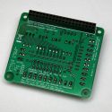
Lo-tech GPIO Interface Board rev.2
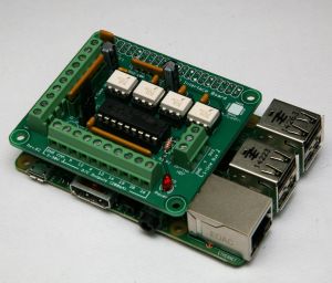
The Lo-tech GPIO Interface Board rev.2 enables the connection of the RaspberryPi Model A+, B+ and the new quad-core Model 2B to the outside world, featuring:
- 4x opto-isolated inputs (3.3 ~ 30V)
- 8x open-collector outputs (3.3 ~ 30V, 200mA) with inductive drive capability
- Maxim 1-wire bus connection (eg for temperature sensor)
- Fused 5V power header (for powering the Raspberry Pi)
The board has been designed to fit directly on top of the RaspberryPi Model B+ following the HAT physical dimensions (this board does not however provide the I2C EEPROM function required for HAT auto-configuration), and supersedes the Lo-tech GPIO Interface Board.
Note: This board is currently available as a bare PCB from stock with no minimum order quantity, and as a finished product with a minimum order quantity of 100 pieces. Please get in touch. for a quote.
Specifications
- Small form-factor:
- Mounts directly to RaspberryPi device and fits within device footprint (65x56mm)
- 2.8mm mounting holes aligned with RaspberryPi device mounting holes
- 11mm spacing between boards (use 11mm standoff)
- Power Options:
- Power from GPIO header - no separate power connection required; entire device powered via micro-USB on Raspberry Pi
- 5V DC provided to screw-terminals on GPIO board - no separate power connection required to the Raspberry Pi. Polyfuse protection is provided (900mA).
- Inputs:
- Four independent opto-isolated inputs with screw terminals
- Input levels: 3.3 ~ 30V
- Outputs:
- Eight Open-Collector outputs with screw terminals
- Optional pull-up resistor on outputs (can be set to 3.3V, 5V, or to external supply via COM terminal)
- Inductive Drive Capable
- Maximum operating frequency: 2MHz
- Maxim 1-wire Bus IO (screw terminals)
- Power LED
- Total assembled weight: 40g (80g, excluding screws, total when mounted on a Raspberry Pi 2)
Note: this board does not provide the auto-configuration capabilities defined in the RaspberryPi HAT specification; GPIOs must be manually configured during program initialisation.
Inputs
GPIO numbering follows the BCM numbering
The board provides four inputs (GPIOs 22, 23, 24, and 27), each interfaced through H11L1M opto-isolators, which feature Schmitt Trigger outputs. The inputs require 2mA drive, which should be set via appropriate value of RN1. Inputs can be up to 30V. Inputs are initialised by setting GPIOs 22, 23, 24 and 27 to input mode with pull-up. RN2 provides in-line protection to the GPIO pins.
| RN1 Value | Suggested Voltage Range | Opto Switch-On Voltage (typical) | Opto Switch-Off Voltage (typical) |
|---|---|---|---|
| 10k | 24 - 30V | 11.3V | 8.9V |
| 6K8 | 14 - 24V | 8.1V | 6.3V |
| 3K3 | 7 - 14V | 4.5V | 3.5V |
| 1K5 | 5 - 7V | 2.6V | 2.2V |
| 1K | <5V | 2.1V | 1.8V |
RN1 is Bourns 4608X-102 type (isolated, 8-pin 4-element)
Note that this board does not provide transient spike protection - inputs must not exceed 30V. When using pre-production samples, do not set the input channels to output mode with this board connected, as damage to the Raspberry Pi may occur.
Outputs
GPIO numbering follows the BCM numbering
The board outputs are driven by a ULN2803A Darlington Transistor Array, which is able to drive inductive loads directly and suppress the kick-back voltage via the internal free wheeling diodes (requires connection of COM terminal to external supply). Initialisation the outputs is achieved by setting GPIOs 5, 6, 12, 13, 16, 19. 20, 21, 26 to output mode.
The eight open-collector outputs are provided via screw terminals, along with GND and COM connections. Should a pull-up be required, RN3 and can added and configured via JP1 to be:
- 1-2: 3V3
- 2-3: 5V
- Open: when COM is connected.
JP1 must be open if external supply is connected to COM terminal - Raspberry Pi will be damaged if this is not observed. When JP1 is not open, pull-up current will be sourced from the Raspberry Pi 5V or 3V3 rails, a high value or RN3 should therefore b0e used (typically 10K).
Each output can sink 200mA; however total sink current should not exceed 600mA. ULN2803A power dissipation rules should also be observed (see ULN2803a Datasheet).
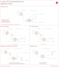
When driving inductive loads, external supply should be connected to COM terminal to enable internal free wheeling diodes to suppress kick-back voltage. Operating voltage should also be de-rated to ensure the maximum voltage does not exceed 30V.
Maxim 1-wire Bus
The board 1-wire bus IO is directly connected to GPIO 4, along with a 4K7 pull-up. Connected temperature sensor(s) can be automatically detected by Linux with appropriate kernel modules installed. When devices are cabled, Cat5e cable is recommended.
Raspbian Kernel Configuration
For 3.18 kernel and newer, a kernel option must be added to /boot/config.txt due to change introduced with the Device Tree system (see this RaspberyPi Forum Post). Add this line to the end of the file, and reboot:
dtoverlay=w1-gpio
Once restarted, kernel modules w1-gpio and w1-therm need to be installed:
pi@raspberrypi ~ $ sudo modprobe w1-gpio
pi@raspberrypi ~ $ sudo modprobe w1-therm
This can be made persistent by adding these module names to /etc/modules. Sensor data is then available via /sys/bus/w1:
pi@raspberrypi /sys/bus/w1 $ find .
.
./devices
./devices/28-000006991886
./devices/w1_bus_master1
./drivers
./drivers/w1_master_driver
./drivers/w1_master_driver/bind
./drivers/w1_master_driver/w1_bus_master1
./drivers/w1_master_driver/uevent
./drivers/w1_master_driver/unbind
./drivers/w1_slave_driver
./drivers/w1_slave_driver/bind
./drivers/w1_slave_driver/28-000006991886
./drivers/w1_slave_driver/uevent
./drivers/w1_slave_driver/unbind
./uevent
./drivers_probe
./drivers_autoprobe
For Dallas 18B20 temperature sensors, 28-000006991886 represents the serial-number of the device (also shown in name), and the current reading is available in w1_slave (28812 in this example is 28.812°C):
pi@raspberrypi /sys/bus/w1/devices/28-000006991886 $ cat name
28-000006991886
pi@raspberrypi /sys/bus/w1/devices/28-000006991886 $ cat w1_slave
cd 01 4b 46 7f ff 03 10 4a : crc=4a YES
cd 01 4b 46 7f ff 03 10 4a t=28812
Bill of Materials
| Part | Value | Device | Package | Qty | Farnell | Mouser |
|---|---|---|---|---|---|---|
| C1..C5 | 0.1uF (100nF) | Ceramic Capacitor | THT | 5 | 2112751 | 581-SR205E104MAR |
| C6..C7 | 10uF | Electrolytic Capacitor | E2-5 | 2 | 8767084 | 647-UVR1C100MDD |
| C8 | Application Dependent | Electrolytic Capacitor | E2-5 | 1 | 8767084 (10uF) | 647-UVR1C100MDD (10uF) |
| HD1, HD2 | 10-way screw terminal (3.81mm) | FCI 20020327-D101B01LF or Kobiconn 158-P02EK381V10-E or Multicomp MC000024 |
THT | 2 | 2007993 | 649-220327-D101B01LF or 158-P02EK381V10-E |
| HD3 | 3-way screw terminal (3.81mm) | FCI 220327-D031B01LF or Kobiconn 158-P02EK381V3-E or Multicomp MC000019 |
THT | 1 | 2007986 | 649-220327-D031B01LF or 158-P02EK381V3-E |
| F1 | LITTELFUSE 30R135UU. POLYFUSE, PTC, 30V, RADIAL, 900MA | 30R090UU | THT | 1 | 1822234 | 576-30R135UU |
| IC1..IC4 | - | H11L1M Optocoupler, Schmitt Trigger | DIP-6 | 4 | 1021127 | 512-H11L1M |
| IC5 | - | ULN2803A Darlington Array | DIP-18 | 1 | 1094428 | 511-ULN2803A |
| JP1 | - | Pin Header, 1x3 | - | 1 | 1593412 | 855-M20-9990346 |
| LED | - | 3mm LED | THT | 1 | 1581112 | 645-521-9432F (red) 859-LTL-2231AT (green) |
| P1 | - | SOCKET, PCB, 0.1", 20+20WAY | THT | 1 | 7992033 | 855-M20-7832046 |
| R1 | 270R | 125mW Carbon Film Resistor | THT | 1 | 2329504 | 299-270-RC or 660-CFS1/4CT52R271G |
| R2 | 4k7 | 125mW Carbon Film Resistor | THT | 1 | 2329534 | 279-CFR16J4K7 |
| RN1 | See table* | SIL-8 Resistor Network (Bournes 4608X-102 type) | THT | 1 | See tables | See tables |
| RN2** | 1k | 4608X-102-102LF | THT | 1 | 9356517 | 652-4608X-2LF-1K |
| RN3 | 10k | SIL-9 Resistor Network (Bournes 4609X-101 type) | THT | 1 | See tables | See tables |
| DIL Socket, 8-pin | - | SOCKET, VERTICAL, 1ROW, 8WAY | THT | 1* | 3419101 | 571-215297-8 or 571-829265-8 |
| IC Socket (DIP18) | - | - | DIL18 | 1 | 2445623 | 571-1-2199298-5 |
| IC Socket (DIP6) | - | - | DIL6 | 4 | 1077343 | 571-1-2199298-1 |
*SIL sockets enable RN1 and RN3 values to be interchanged as required after construction. **Pre-production (engineering sample) boards have RN2 unpopulated.
For values of RN1, see the table in Inputs sections. RN1 component options:
| Value | Part | Farnell | Mouser |
|---|---|---|---|
| 1k | 4608X-102-102LF | 9356517 | 652-4608X-2LF-1K |
| 1k5 | 4608X-102-152LF | 9356568 | 652-4608X-2LF-1.5K |
| 3k3 | 4608X-102-332LF | 9356673 | 652-4608X-2LF-3.3K |
| 6k8 | 4608X-102-682LF | 2321777 | 652-4608X-2LF-6.8K |
| 10k | 4608X-102-103LF | 9356525 | 652-4608X-2LF-10K |
RN3 typically 10K where fitted; other values:
| Value | Part | Farnell | Mouser |
|---|---|---|---|
| 1k | 4609X-101-102LF | 9356800 | 652-4609X-1LF-1K |
| 1k5 | 4609X-101-152LF | 9356851 | 652-4609X-1LF-1.5K |
| 3k3 | 4609X-101-332LF | 9356983 | 652-4609X-1LF-3.3K |
| 6k8 | 4609X-101-682LF | 2321778 | 652-4609X-1LF-6.8K |
| 10k | 4609X-101-103LF | 9356819 | 652-4609X-1LF-10K |
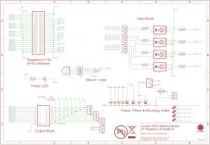
Schematic & Application Notes
Use of this design is provided subject to the lo-tech.co.uk Terms and Conditions. Copyright (c) 2014,2015 Peacon Ltd.
Programming
Any library suitable for use with the Raspberry Pi (models with 40-pin GPIO header) can be used, for example WiringPi. The module is compatible with quad-core Pi2. The GPIO channels used are:
| BCM GPIO | Purpose | Notes |
|---|---|---|
| 4 | Maxim 1-wire Bus | Screw terminals |
| 5 | Open-collector Output | Screw terminal output |
| 6 | Open-collector Output | Screw terminal output |
| 12 | Open-collector Output | Screw terminal output |
| 13 | Open-collector Output | Screw terminal output |
| 16 | Open-collector Output | Screw terminal output |
| 19 | Open-collector Output | Screw terminal output |
| 20 | Open-collector Output | Screw terminal output |
| 22 | Input | See note |
| 23 | Input | See note |
| 24 | Input | See note |
| 26 | Open-collector Output | Screw terminal output |
| 27 | Input | See note |
Note: The specified H11L1M opto-isolator has an LED forward voltage of 1.2V and requires 2mA drive.
