Difference between revisions of "Lo-tech 2MB EMS Board (prototype) Resources"
Jump to navigation
Jump to search
Lo-tech>James (→Design) |
m (1 revision imported) |
(No difference)
| |
Latest revision as of 11:11, 21 April 2021
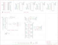
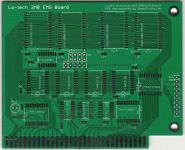
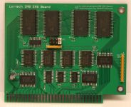
Resources on this page are for the Lo-tech 2MB EMS Board (prototype).
Design
Use of this design is provided subject to the lo-tech.co.uk Terms and Conditions. Copyright (c) 2013 Peacon Ltd.
Bill of Materials
| Part | Value | Device | Package | Qty | Farnell | Mouser |
|---|---|---|---|---|---|---|
| C1..C15 | 0.1uF | X7R Ceramic Capacitor | 0603 | 15 | 1414610 | - |
| C16 | 10uF | 16V Electrolytic | E2-5 | 1 | 9451056 | - |
| IC1, IC5 | - | 74HCT688DW | SOIC-20 | 2 | 1085321 | - |
| IC2 | - | 74HCT139D | SOIC-16 | 1 | 1085308 | - |
| IC3 | - | 74HCT04D | SOIC-14 | 1 | 1085299 | - |
| IC4 | - | 74HCT32D | SOIC-14 | 1 | 1201305 | - |
| IC6..IC9 | - | 74HCT573D | SOIC-20 | 4 | 1201309 | - |
| IC10 | - | 74HCT245DW | SOIC-20 | 1 | 1085315 | - |
| IC11 | - | 74HCT138D | SOIC-16 | 1 | 1201307 | - |
| IC12..IC15 | - | AS6C4008-55SIN 4Mb SRAM | SOIC-32 | 4 | 1562901 | - |
| JP1 | - | PINHD-2X4 | - | 1 | 1593441 | - |
| RN1 | 10k | BOURNS 4609X-101-103LF | SIL-9 | 1 | 2112931 | - |
| RN2 | 10k | BOURNS 4605X-101-103LF | SIL-5 | 1 | 9356061 | - |
JP1: Board Configuration
The board is configured via four jumpers on the pin-header JP1 (O=open, C=closed, position 1 is furthest from IC11 (74LS138D)):
| Page Frame Base Address | IO Port Base Address | ||||||||||||||||||||
|---|---|---|---|---|---|---|---|---|---|---|---|---|---|---|---|---|---|---|---|---|---|
|
|
The recommended configuration is E000h and 260h, being C,O,O,O. Note that F000h cannot be used due to the system BIOS occupying this physical segment.
See Also
- Lo-tech 2MB EMS Board (current version)


