Difference between revisions of "XT-CF-lite rev.1"
Lo-tech>James (Content moved in to XT-CF-Lite page (which is now a redirect)) |
m (1 revision imported) |
(No difference)
| |
Latest revision as of 11:11, 21 April 2021
Note: This adapter has been superseded by the XT-CF-lite rev.2
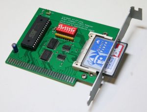
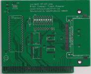
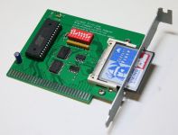
The lo-tech XT-CF-lite rev.1 board is an 8-bit ISA CompactFlash adapter, providing bootable solid-state storage for any IBM compatible PC, including the original IBM Personal Computer 5150. The board has been designed to provide basic functionality in the same footprint as the XT-CFv3, but with SOIC 74xx series logic, thereby eliminating the need to program a CPLD and so simplifying construction.
As with the other lo-tech XT-CF Boards, the CompactFlash card is accessible through a custom-made ISA expansion slot bracket, such that the media can be exchanged without the need to open the PC case.
The board is powered by the XT-IDE Universal BIOS, provided through an in-system re-programmable 32KB (addressible) flash-based ROM. Since the BIOS is only 8KB, 24KB is available for other purposes, and is byte-programmable. The board can therefore function as a universal ROM board, regardless of whether the CompactFlash logic is used (or indeed populated on the PCB).
Specifications
- 8-bit ISA card with header for type-I or type-II CompactFlash media
- CompactFlash header configured to operate media in true-IDE mode
- 5V supply to CompactFlash header can drive micro-drives or CompactFlash cards without any external power connection
- Line driver for on-card and external activity LEDs (30mA power budget for external LED)
- Low-cost flash memory chip for boot ROM, with 32KB usable
- Port-mapped IO; supports both 8- and 16-bit instructions (via partial address decoding)
- Utilises XT-IDE Universal BIOS (adapter type: 'XT-CF')
Design
Use of this design is provided subject to the lo-tech.co.uk Terms and Conditions.
Bill of Materials
| Part | Value | Device | Package | Qty | Farnell | Mouser |
|---|---|---|---|---|---|---|
| C1 | 47uF | CPOL-EUE2-5 | E2-5 | 1 | 8767114 | 140-REA470M1ABK0511P |
| C2..7 | 0.1uF | C-EUC0603 | C0603 | 6 | 1414610 | 81-GRM18R71C104MA01D |
| CF1 | N7E50-Q516 | N7E50-Q516xx-50 | N7E50-Q516xx-50 | 1 | 1267444 | 517-N7E50-Q516B-50-W |
| EXT.LED | HD_LED | PINHD-1X02_2.54-S | 1X02-S | 1 | 3418285 | 571-826629-2 |
| IC1 | - | SST39SF0x0A | DIP32 | 1 | 1896595 | 804-39SF010A7CPHE |
| IC2..3 | - | 74HCT688DW | SO20W | 2 | 1085321 | 771-74HCT688D-T |
| IC4 | - | 74HCT32D | SO14 | 1 | 1201305 | 595-SN74HCT32D |
| IC5 | - | 74HCT04D | SO14 | 1 | 1085299 | 771-74HCT04DAUJ |
| IC6 | - | 74LVC1G14 | SOT-25 | 1 | 1893833 | 771-74LVC1G14GW-G |
| LED | LEDCHIPLED_0805 | CHIPLED_0805 | 1 | 1685055 | 630-HSMR-CL25 | |
| R1 | 0R | R-EU_0207/10 | 0207/10 | 1 | 1700196 | 299-0-RC |
| R2 | DNP | - | - | - | - | - |
| R3, R5 | 1k | R-EU_R0603 | R0603 | 2 | 2008355 | 667-ERA-3AED102V |
| R4 | 160R | R-EU_R0603 | R0603 | 1 | 2059585 | 71-CRCW0603-270-E3 |
| R6 | 5.6k | R-EU_R0603 | R0603 | 1 | 1739171 | 667-ERA-3AED562V |
| RN1 | 10K | RN08 | RN-9 | 1 | 9356819 | 652-4609X-1LF-10K |
| SW1 | SW_DIP-8 | EDG-08 | 1 | 9471596 | 774-2068ST | |
| Socket | DIL32 | 1 | 1654375 | 571-1-390263-2 |
- Board design permits the use of a range of DIP-32 flash chips or 1, 2 or 4Mb:
- SST39SF0x0A (SST39SF010A, SST39SF020A, SST39SF040A)
- AMIC A29010
- Regardless of the chip used, the first 32KB only will be mapped into the PC address space
- Base address configuration per DIP Switch Settings
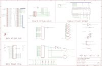
Logic
The board logic provides two distinct functions:
- Address decoding for the SST39SF0x0 flash chip
- Address bus is matched to DIP switch settings via IC2, to generate ROM chip-enable
- Address decoding for the CompactFlash header /CS0 and /CS1, via IC3, IC4 and IC5
- Address bus is matched to DIP switch settings via IC3
- CompactFlash header /CS0 and /CS1 are generated using logic similar to the Vintage-Computer XT-IDE Board, providing Base+10h for the alternate status register access
- CompactFlash header /DA[0..2] are mapped to ISA A[1..3], thereby enabling 16-bit instructions, since A0 is not decoded
BIOS
- The board is fully supported by the XT-IDE Universal BIOS
- Port configured via DIP switches must be entered in the XT-IDE Universal BIOS Configuration Utility
- ROM images can be managed with the Lo-tech XT-CF flash utility
- Beta BIOS (configured for IO port 300h)
ISA Bracket
Uses Lo-tech ISA Slot Bracket Type 1.
DIP Switch Settings
| Switch | Function | On | Off |
|---|---|---|---|
| 1 | ROM Enable | Enabled | Disabled |
| 2 | ROM Base Address A15 | Low | High |
| 3 | ROM Base Address A16 | Low | High |
| 4 | ROM Base Address A17 | Low | High |
| 5 | IO Port A5 | Low | High |
| 6 | IO Port A6 | Low | High |
| 7 | IO Port A7 | Low | High |
| 8 | IO Port A8 | Low | High |
Default settings are ROM enabled, IO port 300h and ROM base address D000h:
| 1 | 2 | 3 | 4 | 5 | 6 | 7 | 8 |
|---|---|---|---|---|---|---|---|
| ON | ON | OFF | ON | ON | ON | ON | OFF |
IO Range
| IO Port Base Address | Sw8 | Sw7 | Sw6 | Sw5 |
|---|---|---|---|---|
| 200h | ON | ON | ON | ON |
| 220h | ON | ON | ON | OFF |
| 240h | ON | ON | OFF | ON |
| 260h | ON | ON | OFF | OFF |
| 280h | ON | OFF | ON | ON |
| 2A0h | ON | OFF | ON | OFF |
| 2C0h | ON | OFF | OFF | ON |
| 2E0h | ON | OFF | OFF | OFF |
| 300h* | OFF | ON | ON | ON |
| 320h | OFF | ON | ON | OFF |
| 340h | OFF | ON | OFF | ON |
| 360h | OFF | ON | OFF | OFF |
| 380h | OFF | OFF | ON | ON |
| 3A0h | OFF | OFF | ON | OFF |
| 3C0h | OFF | OFF | OFF | ON |
| 3E0h | OFF | OFF | OFF | OFF |
*Default
Note that the IO base address is set within the XTIDE Universal BIOS ROM image via the Universal BIOS Configuration and Flashing utility. The IO address set within that utility must match that configured on the card via the DIP switches. Should the IO port address be changed for any reason, the BIOS must be updated and re-flashed to the XT-CF-lite card (using the lo-tech XT-CF flash utility).


