Lo-tech 8-bit ROM Board
Note: This board has been superseded by the Lo-tech ISA ROM Board.
The lo-tech 8-bit ROM Board is a simple and cheap to make (both in terms of the PCB and the components) 8-bit ISA board that provides a 32 or 64KB ROM via a flash chip, which can be (re)programmed a practically limitless number of times directly within the host PC via the lo-tech XT-CF flash utility.
The board can be used to store any ROM image (or images) in any PC with an ISA slot. The DIP switches allow an address base selectable between 8000h and F800h and configuration as either 32KB or 64KB.
The board uses entirely through-hole components for simple home assembly.
PCB
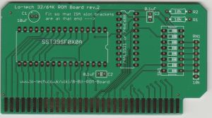
The rev.2 PCB is almost identical to the original version, with just a few trace routing changes. Both have the same BoM.
Boardhouse Requirements
- 8 mils clearances and minimum track width
- 0.4mm minimum hole size
- Can be manufactured on a 50x100mm board
- Gold fingers are preferable but not required
Assembly Notes
- Thoroughly wash the PCB before assembly with Isopropynol
- Generally, work from the smallest components to the largest, so that they are held in place by the work-surface when soldering
- The use of syringe flux will make it easier to get good joints
- When soldering multi-pin components (such as the IC sockets), solder one pin (only) then check the physical placement before continuing, as adjustment later is difficult
- Guideline order of assembly:
- Resistors R1 & R2
- Capacitors C2 & C3
- IC sockets (note orientation via notch - align to silkscreen)
- Resistor network RN1 (datasheet) - mount so the end with the dot (pin 1) is nearest to the ISA edge connector
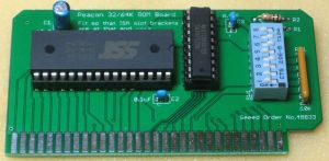
- DIP switch (note orientation to board photo, to ensure switch numbers tally to configuration settings below)
- Electrolytic capacitor C1 (note orientation!)
- The DIP switch supplied in the kit is washable, so the board can be thoroughly cleaned to remove flux residues with a toothbrush in isopropynol once fully assembled.
- Fit the to ICs in the sockets, noting orientation via the notch (also refer to the constructed board photo). The IC pins will need to be bent to 90° - with the IC on it's side with a row of pins against a smooth work-surface, gently push down and twist the body until such alignment is achieved
Bill of Materials
| Mouser Part No | Description | Quantity |
|---|---|---|
| 804-39SF010A7CPHE | SST39SF0x0A or AMIC A29010 Flash (DIP32) | 1 |
| 21RZ310-RC | Ceramic Capacitors 0.1uF Z5U 20% 2.5mm L/S | 2 |
| 140-REA100M1EBK0511P | Electrolytic Capacitor 10uF 20% 5x11mm | 1 |
| 774-2068ST | DIP Switch SPST 8-way | 1 |
| 571-1-390263-2 | 32P DIP Socket | 1 |
| 571-1-390261-6 | 20P DIP Socket | 1 |
| 595-SN74F521N | SN74F521N Comparitor | 1 |
| 652-4607X-1LF-10K | Resistor Network 7 pins 10Kohms Bussed | 1 |
| 279-CFR25J10K | Carbon Film Resistor 10KOhm 1/3W | 2 |
- Board design permits the use of a range of DIP-32 flash chips or 1, 2 or 4Mb:
- SST39SF0x0A (SST39SF010A, SST39SF020A, SST39SF040A)
- AMIC A29010
- Regardless of the chip used, the first 32KB or 64KB (only) will be mapped into the PC address space
- Base address configuration per DIP Switch Settings
DIP Switch Settings
Summary
| Switch | Function | On | Off |
|---|---|---|---|
| 1 | ROM Write Enable | Enabled | Disabled (ROM cannot be erased or written) |
| 2 | ROM Enable | Enabled | Disabled |
| 3 | ROM Base Address A15 | Low | High |
| 4 | ROM Base Address A16 | Low | High |
| 5 | ROM Base Address A17 | Low | High |
| 6 | ROM Base Address A18 | Low | High |
| 7 | Flash Chip A15 Source | ISA Bus A15 | Low |
| 8 | Comparitor A15 Source | ISA Bus A15 | Low |
- For 32KB operation, set 3 as required, 7 Off and 8 On
- For 64KB operation, set 3 On, 7 On and 8 Off
32KB Address Mapping
| Base Address | Sw3 | Sw4 | Sw5 | Sw6 | Sw7 | Sw8 |
|---|---|---|---|---|---|---|
| 8000h* | On | On | On | On | Off | On |
| 8800h* | Off | On | On | On | Off | On |
| 9000h* | On | Off | On | On | Off | On |
| 9800h* | Off | Off | On | On | Off | On |
| A000h | On | On | Off | On | Off | On |
| A800h | Off | On | Off | On | Off | On |
| B000h | On | Off | Off | On | Off | On |
| B800h | Off | Off | Off | On | Off | On |
| C000h | On | On | On | Off | Off | On |
| C800h | Off | On | On | Off | Off | On |
| D000h | On | Off | On | Off | Off | On |
| D800h | Off | Off | On | Off | Off | On |
| E000h | On | On | Off | Off | Off | On |
| E800h | Off | On | Off | Off | Off | On |
| F000h | On | Off | Off | Off | Off | On |
| F800h | Off | Off | Off | Off | Off | On |
* Note that these ranges aren't valid for option ROMs in PC architecture.
64KB Address Mapping
| Base Address | Sw3 | Sw4 | Sw5 | Sw6 | Sw7 | Sw8 |
|---|---|---|---|---|---|---|
| 8000h* | On | On | On | On | On | Off |
| 9000h* | On | Off | On | On | On | Off |
| A000h | On | On | Off | On | On | Off |
| B000h | On | Off | Off | On | On | Off |
| C000h | On | On | On | Off | On | Off |
| D000h | On | Off | On | Off | On | Off |
| E000h | On | On | Off | Off | On | Off |
| F000h | On | Off | Off | Off | On | Off |
* Note that these ranges aren't valid for option ROMs in PC architecture.
Sample ROM Image Files
8-bit IDE
A customised build of the XTIDE Universal BIOS (based on build r443) to enable CompactFlash media to be used connected to a standard 16-bit ISA IDE controller but installed in an 8-bit XT-class machine. The IDE controller must be using standard ports 1F0h and 3F0h.
Testing with with Diamond Flower MIO-400 KF REV F and Goldstar Prime 2 controllers, and expected to work with any standard IDE controller using the specified port addresses.
See http://code.google.com/p/xtideuniversalbios for official builds of the XTIDE Universal BIOS and source code.
High-Density Floppy
XT compatible BIOS images to run high-density floppy drives, for example from 16-bit ISA multi-IO cards.
- FDC-BIOS.zip (courtesy of http://n8vem-sbc.pbworks.com)
- DTK-FDC-BIOS.zip (extracted from an 8-bit HD-FDC controller)

