Lo-tech 8-bit IDE Adapter rev.2

The Lo-tech 8-bit IDE Adapter rev.2 is a bootable storage adapter for IBM PC, PC/XT, PC/AT and compatible hardware - essentially any PC with an ISA slot. The card enables the use of standard IDE (ATA) and SATA hard drives (via a SATA to IDE bridge).
The BIOS ROM on the card enables the host PC to boot from storage presented by the adapter, which appears in DOS as an ordinary fixed disk (i.e. drive C, D, etc). No DOS drivers are needed.
The PCB itself is a through-hole, 8-bit ISA adapter providing a 40-pin IDE header suitable for connection to one or two disk devices. The design goals were:
- Bootable storage adapter for 8-bit PCs using standard hard disks
- Ease of home assembly, by use of only through-hole components for basic operation
- IBM Personal Computer XT System Board Slot 8 compatibility (with optional SMD components mounted on rear of PCB)
- 5V supply to IDE header key-pin, for cable-less operation of Disk-On-Module devices and SATA to IDE Adapters that support this power option
- Equal read and write speed
The board uses the same ATA register mapping as other Lo-tech XT-CF boards and uses the XT-IDE Universal BIOS adapter type 'XT-CF (PIO with BIU Offload)' (XT-CF BIU). Note that currently, a specific BIOS build is used, pending integration of changes back into the XTIDE Universal BIOS source. The BIOS is provided through an in-system re-programmable 32KB flash-based ROM operating at either C800h or D800h (user selectable). Since the BIOS is only 8KB, 24KB is available for other purposes, and is byte-programmable - the board can therefore function as a universal ROM board.
This PCB is available now in the Lo-tech PCB Store.
If only CompactFlash or SD Card storage is required, the Lo-tech ISA CompactFlash Adapter offers equivalent functionality with a lower component count. This board supercedes the Lo-tech 8-bit IDE Adapter.
Jumper Settings & System Resources
- ROM BIOS - 32KB at:
- JP1 Closed, JP2 Closed: C800h
- JP1 Closed, JP2 Open: D800h
- ROM BIOS can be disabled (for example, if a bad flash causes system hang at startup) by opening JP1.
- IO Ports - 300 to 31Fh (fixed)
ROM BIOS & BIOS Flashing
- The board is powered by the XT-IDE Universal BIOS and features a 32KB in-system re-programmable flash chip.
- Pre-configured BIOS files based on XTIDE Universal BIOS R567. Note that this BIOS has been modified for the 8-bit IDE Adapter by disabling the 8-bit media set function (AH9h_Enable8bitModeForDevice8bitAta).
- The flash chip is programmed with the Lo-tech XT-CF flash utility
- Select the appropriate ROM image:
- IDE_XT.BIN for Intel 8088 and 8086 CPUs
- IDE_XTP.BIN for NEC V20, V30, and Intel 80286 CPUs
Note: The late initialisation module in the XTIDE Universal BIOS should only be included in the BIOS build for systems that require this. The module can cause the BIOS to hang after initialisation on other systems. The BIOS build above excludes this module.
To program the board, make a DOS boot disk (utilities have been tested on MS-DOS 2.11, 3.3 and 6.22) and add the BIOS binary files and the flash utility from the download. Install the Lo-tech 8-bit IDE Adapter in the machine and boot from the floppy, then flash the ROM thus:
A:\>flash ide_xt.bin c800
Note that should a board containing the IDE_XTP.BIN image be moved to an Intel 8088/8086 PC, the BIOS image will cause the machine to hang during the POST. To resolve this, either re-flash the board with the IDE_XT.BIN image before moving, or disable the ROM during the POST via JP1. JP1 can be closed once the machine has booted, so enabling the ROM for programming (provided there is no other ROM at the address selected with JP2).
Bill of Materials
| Part | Device | Package | Qty | Farnell | Mouser |
|---|---|---|---|---|---|
| C1 – C14 | 0.1uF Ceramic Capacitor | C025-030X050 | 14 | 2112751 | 581-SR205E104MAR |
| C15, C16 | 22uF Electrolytic Capacitor | E2-5 | 2 | 9451064 | 647-UVR1C220MDD |
| HD1 | T821140A1S100CEU | 2x20 Pin Header, 2.54mm spacing | 1 | 2215314 | 517-30340-6002 |
| IC1, IC3 | 74HCT688N | DIL20 | 2 | 382504 | 771-74HCT688N |
| IC2 | SST39SF010ADIP32 | DIL32 | 1 | 1896595 | 804-39SF010A7CPHE |
| IC4 | 74HCT139N | DIL16 | 1 | 382036 | 595-SN74HCT139N |
| IC5, IC8, IC9 | 74HCT245N | DIL20 | 3 | 9591931 | 595-SN74HCT245N |
| IC6, IC7 | 74HCT573N | DIL20 | 2 | 9592091 | 595-SN74HCT573N |
| IC10, IC12 | 74HCT32N | DIL14 | 2 | 9591982 | 595-SN74HCT32N |
| IC11 | 74HCT02N | DIL14 | 1 | 1740019 | 595-SN74HCT02N |
| IC13 | 74HCT04N | DIL14 | 1 | 9591770 | 595-SN74HCT04N |
| IC14 | 74LS04N | DIL14 | 1 | 1106072 | 595-SN74LS04N |
| JP1, JP2, LED | PINHD-1X2 | 1X02 | 3 | 1593411 | 855-M20-9990246 |
| R1, R2, R4 | RESISTOR, 10K, 125MW | 0204/7 | 3 | 9342419 | 270-10K-RC |
| R3 | RESISTOR, 1K, 125MW | 0204/7 | 1 | - | 270-1K-RC |
| R5 | RESISTOR, 5K6, 125MW | 0204/7 | 1 | - | 270-5.6K-RC |
| R6 | RESISTOR, 0.125W 1% 270R | 0204/7 | 1 | 2329504 | 270-270-RC |
| R7, R8 | RESISTOR, 10K, 125MW | 0805 | 2 | 1612522 | 71-CRCW0805J-10K-E3 |
| U1 | 74LS33D | SOIC-14 | 1 | 1752958 | 595-SN74LS33D |
| C17 | CAPACITOR, 0.1UF, 50V | 0805 | 1 | 1612208 | VJ0805V104MXBPW1BC |
| DIP-14 Socket | - | - | 5 | 1101346 | 571-1-390261-3 |
| DIP-16 Socket | - | - | 1 | 1101347 | 571-1-390261-4 |
| DIP-20 Socket | - | - | 7 | 1101349 | 571-1-390261-6 |
| DIP-32 Socket | - | - | 1 | 1654375 | 571-1-2199300-2 |
| 2.54mm 2-pin Jumper | - | - | 2 | 1654800 | - |
Design
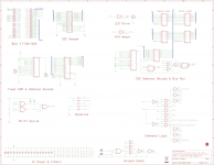
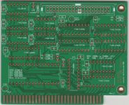
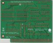
- Lo-tech-8-bit-ide-adapter-rev2-assembled.jpg


Use of this design is provided subject to the lo-tech.co.uk Terms and Conditions.
ISA Bracket
Uses Lo-tech ISA Slot Bracket Type 3.