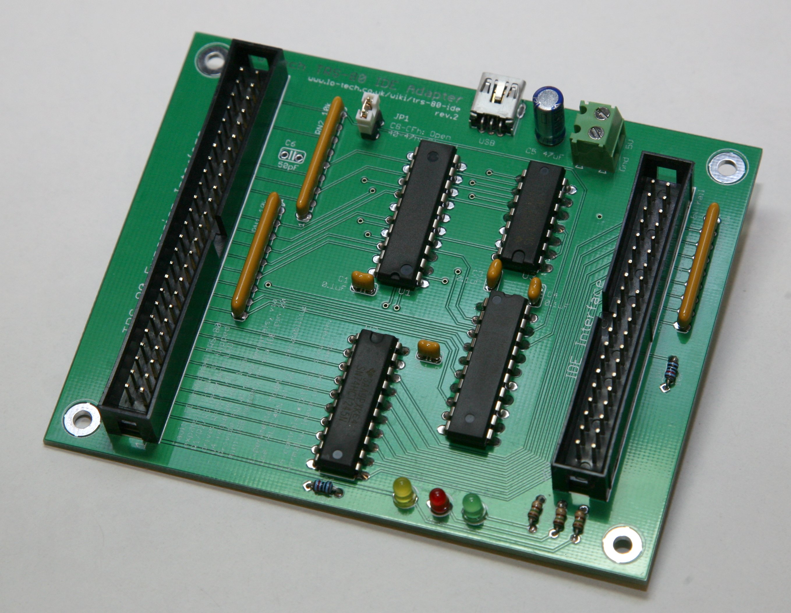
The Lo-tech TRS-80 IDE adapter is an external IDE storage adapter for Tandy TRS-80 model 3/4/4P PCs, enabling connection of standard IDE drives (and CompactFlash cards, with an adapter).
A limitation has been that the machines needed to be booted from floppy disk still, since there is no HDD boot code in the Model 3 and 4 ROMs, and the HDD boot code in the 4P ROM is expecting a WD1010 controller rather than an ATA drive.
Community to the rescue as Audronic, Gazza and Hans have burnt plenty of midnight oil patching the 4P ROM with enough code to get LSDOS 6.3.1 to start up directly from the Lo-tech adapter! Here it is in action:
Currently this has been tested with a number of hard disks (full list in the download) but doesn’t currently work with SD cards. Some DoM devices can though be used, this one having been tested OK. Gazza has kindly put together a RAR achive with the patched ROM binary along with very detailed documentation, which is available via the Lo-tech wiki now.
No more floppy disks needed for your 4P!
Product links have been included here for convenience; Lo-tech has no connection with the sellers.
It turns out there’s already a bootable IDE solution, the FreHD project, providing access to disk images stored on a FAT32 formatted SD card powered by a PIC microcontroller. It does look fantastic, but I felt there could be space for something simpler (and so cheaper) as well.
The prototyped low-cost adapter needs just a few 7400 series ICs, and simply ignores half the data coming from the IDE device to provide the 256-byte sectors the TRS-80 expects. The designer though notes some compatibility issues:
I did have one problem, though — not all IDE drives would work….only one of the four IDE drives I tried would work.
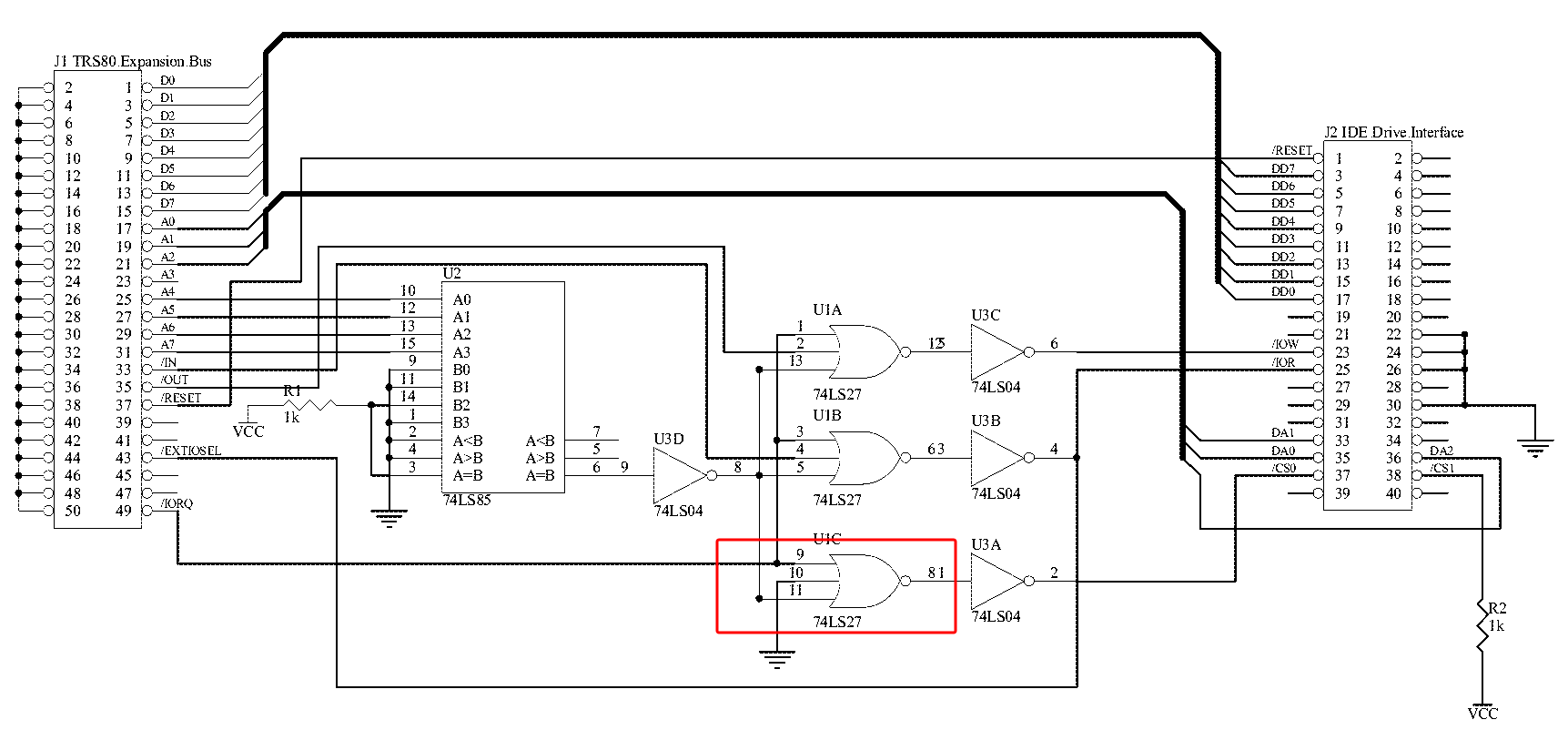
When the CPU accesses a device, it first provides the address (IO Port) then the read or write signal. In the Z80 world the CPU generates the same address, read (RD) and write (WR) signals for memory or IO port addressing, the two being distinguished with IO-Request (IORQ) or Memory Request (MREQ) signals.
In the TRS-80 expansion interface (model 3/4/4P), the system combines IORQ, RD and WR signals to provide simple IN and OUT signals along with the address bus, also providing IORQ and M1 signals for reference which can be used to identify interrupt acknowledgement.
In the original design it seems that device compatibility issues might have been caused by the inclusion of IORQ in the address matching logic:
IORQ is asserted concurrently with IN or OUT, so the logic has a timing issue since the IDE interface expects its chip-select (i.e. address match) line to have been asserted before the read or write command.
The Lo-tech design follows more the the XT-CF design, with the IDE chip-select line being driven directly from the address bus with just an LS688 comparator. Some prototyping work by vcforum member Chromedome45 soon proved the logic – so the Lo-tech TRS-80 IDE Adapter PCB design:
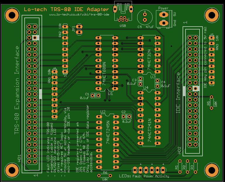
Lo-tech TRS-80 IDE Adapter (image generated with GerbV)
Further information on the board including bill of materials, device drivers and design files can be found on the Lo-tech TRS-80 IDE Adapter wiki page.
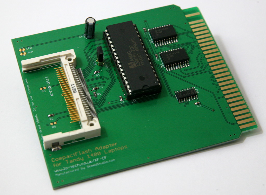
Tandy helpfully included an expansion slot in their 1400 series of laptops, and in places there is reference to an expansion box, but it seems it never made it to market. The later 1400FD and 1400HD models retained the expansion slot and added a second (slightly different) slot for an MFM HDD controller, as implemented in the 1400HD.
The expansion slot is basically an 8-bit ISA slot, but with a different pinout and a few differences, in a custom card form factor to fit in the machine. Power budget is also limited to 200mA, according to the service manual. Fortunately, Tandy documentation provides everything needed to create a card – so here is what I believe to be the first ever expansion card for Tandy 1400 Series laptops (only about 20 years late):
Expansion Card Design
Based on the information available in the Tandy technical reference, I’ve created a wiki page detailing everything about the expansion slots. Some of the Tandy documentation is contradictory, but my wiki is based on what is now a proven design. I’ve also included an Eagle layout for the PCB (restricted to a 100 x 100mm footprint, to enable low-cost manufacture by SeeedStudio).
XT-CF
My XT-CF cards provide hard disk functionality to PC/XT and PC/AT class machines based on CompactFlash (or microdrives), and for the Tandy 1400 the design needs just four ICs – a flash ROM, two 74688 address decoders and a 74139 decoder. Being XT-CF compatible, the design is fully supported by the XTIDE Universal BIOS (from build r554).
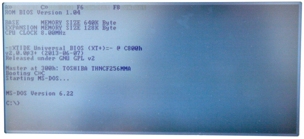
BIOS Initialisation
I built this board a while back, and although BIOS flashing went OK the machine didn’t want to initialise the XTIDE Universal BIOS. The BIOS was clearly detecting the option ROM as the floppy seek test was performed on only the first floppy with it present (the BIOS assuming that an HDD would be installed in place of the second floppy, exactly as the 1400HD was shipped), but the BIOS initialisation messages never appeared.
This has had me stumped and the board simply sat on the side since. But recently XTIDE Universal BIOS project lead Tomi posted a code update (in r552):
XTIDE Universal BIOS can now be initialized if non-standard main BIOS does not call INT 19h or if INT 19h handler is replaced by some other BIOS.
And sure enough, the BIOS fired into life and the machine booted (and yes, the SuperTwist LCD screen really does look this bad):
The solution isn’t quite perfect – the fixed disk is inaccessible when restarted via CTRL-ALT-DELETE, but since boot time on this machine is identical for both soft boot and cold boot, this is just something that we need to live with for now.
1400LT, 1400FD and 1400HD
For 1400FD systems at least with BIOS 1.04, the system BIOS assumes the second floppy isn’t installed when the XT-CF option ROM is present (this may also affect 1400LT systems). For now this is a limitation, but with 32KB of flash ROM available it should be possible to resolve it by adding a floppy BIOS to the card.
For 1400HD machines, the MFM controller must be removed since both cards have their BIOS at C800h (upper memory space is somewhat limited in the 1400 series as Tandy included RAM in the upper memory area for use as a RAM disk).
Performance
Using the ‘XTplus’ XTIDE Universal BIOS build (thanks to the V20 CPU), DOS throughput (as measured with my own test utility) is at least 550KB/s. Due to the 8-bit data bus and V20 microcode optimisations, there is no performance difference between standard 8-bit PIO and BIU offload modes (as set with XTCFMODE), although both modes are supported.
Availability
ENIG PCBs (gold plated) are available now through the shop page.
Components will also be needed from your local electronics outlet such as Farnell, Mouser or Digikey – full Bill of Materials in the wiki. There is no bracket needed, since the card slides into the expansion slot guides within the system chassis, and the fit into the slot is tight enough not to need and further support.
This website uses cookies to improve your experience. We'll assume you're ok with this, but you can opt-out if you wish.AcceptRead More
Privacy & Cookies Policy
Privacy Overview
This website uses cookies to improve your experience while you navigate through the website. Out of these, the cookies that are categorized as necessary are stored on your browser as they are essential for the working of basic functionalities of the website. We also use third-party cookies that help us analyze and understand how you use this website. These cookies will be stored in your browser only with your consent. You also have the option to opt-out of these cookies. But opting out of some of these cookies may affect your browsing experience.
Necessary cookies are absolutely essential for the website to function properly. This category only includes cookies that ensures basic functionalities and security features of the website. These cookies do not store any personal information.
Any cookies that may not be particularly necessary for the website to function and is used specifically to collect user personal data via analytics, ads, other embedded contents are termed as non-necessary cookies. It is mandatory to procure user consent prior to running these cookies on your website.
Lo-tech products are sold via TexElec. Please visit their web site texelec.com. Dismiss